FREE SHIPPING on orders OVER $250
Use code SHIP4FREE at checkout


 888-568-1230
Fast Lead Times | Fast Shipping


 Category 5 / 5E & Cat 6 Cabling Tutorial and FAQ's
The following article aims to provide beginner to intermediate-level installers with just the right mix of technical and practical information on Category 5, Category 5e, and Category 6 UTP network cabling. Please look for our upcoming tutorial on Category 6A and 10 Gigabit UTP cabling.
The information presented in this article does not cover all details necessary to complete a fully compliant TIA-568B installation that would require reading the entire standard. It does, however, touch upon what I believe to be the most important aspects you need to know. To ensure that you fully understand all of the information, I strongly suggest reading the entire article, including the definitions. Even the intermediate-level installer may discover useful facts they were previously not aware of. Please note that this article is for general information only. Always check with local code officials, and / or cabling consultants when planning a network cabling installation.
This article applies to Category 5, Category 5e (Cat 5 Enhanced), and Category 6 cables. When reference is made to UTP network cable, we are referring to all three categories. Please also be aware that the terms Category and Cat are used interchangeably throughout this article to refer to cabling types.
Key Definitions |
|
|---|---|
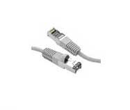
UTP (Unshielded Twisted Pair) |
Used primarily for data transmission in local area networks (LANs), UTP network cable is a 4-pair, 100-ohm cable that consists of 4 unshielded twisted pairs surrounded by an outer jacket. Each pair is wound together for the purposes of canceling out noise that can interfere with the signal. UTP cabling systems are the most commonly deployed cable type in the U.S. |
F/UTP (foil unshielded twisted pair) |
F/UTP cable consists of four unshielded twisted pairs surrounded by an overall foil shield. F/UTP has also been referred to as ScTP (screened twisted pair) and FTP (foiled twisted pair). F/UTP cable is not as common as UTP, but is sometimes deployed in environments where electromagnetic interference (EMI) is a significant concern. With shielded systems, the foil shield must maintain continuity throughout the entire system. |
S/FTP (shielded foil twisted pair) |
S/FTP consists of four foil-shielded twisted pairs surrounded by an overall braided shield. This fully shielded cable is often referred to as PiMF (pairs in metal foil), or SSTP. It is the primary cable type deployed in Europe, but rarely seen in the U.S. With shielded systems, the foil shield must maintain continuity throughout the entire system. |
Category 5 Cable |
Category 5e cable is an enhanced version of Category 5 that adheres to more stringent standards (see comparison chart below). It is capable of transmitting data at speeds of up to 1000 Mbps (1 Gigabit per second). |
>568B Standard
Published in 2001, the TIA-568B standard sets minimum requirements for the various categories of cabling. The 568 "standard" is not to be confused with 568A or 568B wiring schemes, which are themselves part of the standard.
> 568A & 568B Wiring Schemes
When we refer to a jack or a patch panel's wiring connection, we refer to either the 568A or 568B wiring scheme, which define the pin-pair assignments for terminating UTP cable.
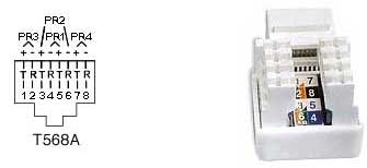
So, when someone refers to 568B, are they talking about the standard or the wiring scheme? It depends on the context. If someone were to say, "The entire office fully complies with 568B," they would be talking about the standard. If someone were to say, "The jacks and patch panels are all 568B, they would likely be referring to the wiring scheme. In UTP cable, each pair is represented by a specific color. Pair 1 is Blue, Pair 2 is Orange, Pair 3 is Green, and Pair 4 is Brown. In each pair, one wire is a solid color, and the other is predominantly white with a color stripe. When terminating UTP, each pair corresponds to a specific pin on the IDC contacts of the jack or patch panel, depending on which wiring scheme is used. The only difference between 568A and 568B is that Pairs 2 and 3 (orange and green) are swapped. The following charts illustrate the difference between the A and B methods. For those not familiar with telephony, tip (T) refers to the positive (+) side, and ring (R) refers to the negative side of the circuit.
568A Wiring
| Pair # | Wire | Pin # |
|---|---|---|
| 1 - White / Blue | White / Blue | 5 |
| Blue / White | 4 | |
| 2 - White / Orange | White / Orange | 3 |
| Orange / White | 6 | |
| 3 - White / green | White / green | 1 |
| green / White | 2 | |
| 4 - White / brown | White / brown | 7 |
| brown / white | 8 |
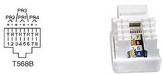
568B Wiring
| Pair # | Wire | Pin # |
|---|---|---|
| 1 - White / Blue | White / Blue | 5 |
| Blue / White | 4 | |
| 2 - White / Orange | White / Orange | 1 |
| Oranage / White | 2 | |
| 3 - White / Green | White / Green | 3 |
| White / Brown | 6 | |
| 4 - White / Brown | White / Brown | 7 |
| Brown / White | 8 |
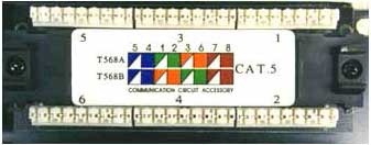
As you can see, the wiring diagrams imprinted on the jacks show both the A & B wiring methods. The back of the patch panel also shows both wiring methods, as seen below.
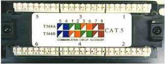
Only the Orange and Green pairs are interchanged from the A to the B method.
Its important to note that there is absolutely no difference between the two wiring schemes in terms of performance when connected from one modular device to another (jack to patch panel, RJ45 to RJ45, etc.) so long as the two devices are wired for the same scheme (pins 1 through 8 on one end are connected to pins 1 through 8 on the other end). The only time one scheme has an advantage over the other is when one end of a network link is connected to a modular device, and the other end to a punch block. In this case, the 568A wiring scheme provides a more natural progression of pairs at the punch block.
The TIA-568 standards committee decided to allow both wiring methods (568A & 568B) to exist within the 568B standard. This was done because many existing cabling plants were installed to the B standard (formerly known as WECO or AT&T 258A), and yet the standard recommends the 568A wiring scheme as the preferred method for all new installations. However, popular opinion went in the other direction, and the most popular wiring method today remains 568B. In my opinion, having both methods does nothing but cause errors and confusion. So which wiring scheme to choose? As we stated earlier; there is no difference between the two wiring schemes in connectivity or performance, so it doesnt really matter.
However, if you are terminating one end onto a punch block, the A method has the advantage. The most critical aspect is that you choose one method and stick with it. I recommend to all installers that wherever feasible, they terminate a link on both the jack and patch panel sides, and then test for proper continuity. Many times an entire installation is terminated only for the installer to then discover that the two ends of the links were wired for different methods. This requires reterminating all of the cables on one end to correct the problem.
UTP Installation Do's and Don'ts.
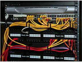
Run all cables in a Star Configuration so that all network links are distributed from, or homerun to, one central hub. Visualize a wagon wheel where all of the spokes start from on central point, known as the hub of the wheel.
Keep Each cable run must be kept to a maximum of 295 feet (90 meters), so that with patch cords, the entire channel is no more than 328 feet (100 meters). This is a requirement of the standard.
Keep Each cable run must be kept to a maximum of 295 feet (90 meters), so that with patch cords, the entire channel is no more than 328 feet (100 meters). This is a requirement of the standard.
Maintain the twists of the pairs as close as possible to the point of termination, or no more than 0.5"(one half inch) untwisted.
Skin off more than 1" of jacket when terminating UTP
Notes and Explanations for Do's and Don'ts
Think of a UTP network link as an extension cord to extend a network switch port to a remote location. If all of the computers and devices were located reasonably close to the switch, we would be able to connect them directly with patch cables. In most cases, this would not be practical. We therefore install cable links to remote locations from patch panels that connect the cable links to switch ports in an organized manner.
Ideally, the network link that we install should smoothly transmit data from one end to another without altering the signal transmitted from device to device in any way. Consider this fact to be Rule #1. There are many technical processes that involve transmitting data over UTP cabling. All you need to know as an installer are a few simple facts. Almost all of the dos and donts described above are specifically designed to adhere to Rule #1. The others are necessary to promote a neat, orderly, safe, and professional installation.
I strongly recommend that anyone who installs UTP cabling take the rules very seriously. An ill planned, or poorly installed cable plant, can easily become a nightmare in the future. Please also be aware that the faster the data speed, the more important the rules become. Many poorly done installations can run 10 Mbps with ease, but they may run into trouble when the network is upgraded to run higher data speeds.
Category 5, 5e, and 6 Performance Specification Chart
Parameter
Category 5 and class D
with additional requirements TSB95 and FDAM
2
Category 5e
(‘568-A-5)
Category 6 Class E
(Performance at 250 MHz shown in
parentheses)
Specified frequency range
1-100 MHz
1-100 MHz
1-250 MHz
Attenuation
24 dB
24 dB
21.7 dB (36 dB)
| Parameter | Category 5 and class D with additional requirements TSB95 and FDAM 2 | Category 5e (‘568-A-5) | Category 6 Class E (Performance at 250 MHz shown in parentheses) |
|---|---|---|---|
| Specified frequency range | 1-100 MHz | 1-100 MHz | 1-250 MHz |
| Attenuation | 24 dB | 24 dB | 21.7 dB (36 dB) |
Note: Requirements for Category 7 are currently under development.
Frequently Asked Questions
| A: | Possible Cause | Test | Repair |
|---|---|---|---|
| 1 | Bad patch cable: Hub side or user side | Test the line with the same patch cables attached. | If in doubt, change both patch cables |
| 2 | Bad Hub port | Plug the line into a different hub port | If you find bad hub port, block it off somehow and use a different port |
In Closing
We hope that you have found this article helpful. I realize that this type of project can seem rather complicated to someone who has never done it before. The truth is that it is really very simple. If you follow the rules and suggestions presented in this article, you should not have any problems. We here at LANshack.com sell just about everything you will need to do an installation. We hope that you will consider us when purchasing your supplies.