SALES & ORDERS
Custom Cable Manufacturing in the USA Since 1997
Home of 
Free Ground shipping on orders over $250

Use code SHIP4FREE Exclusions Apply
Important!
Eligible Products Only | Free Shipping Exclusions May Apply to Heavy, Electronics & Bulky ItemsFast Lead Times/ Fast Shipping
888-568-1230- Pre-Terminated Fiber Optic Assemblies
- back
- In Stock Pre-Terminated
- Indoor Plenum
- Indoor / Outdoor
- Indoor Plenum Interlock Armor
- Indoor Ultra Thin Armored
- I/O Plenum Interlock Armor
- Indoor / Outdoor Ultra Thin Armored
- Outdoor SST Drop Self Supporting
- Outdoor Loose Tube (OSP)
- Outdoor Gel Filled (OSP)
- Outdoor Ultra Thin Armored (OSP)
- Outdoor Armored Direct Burial (OSP)
- Outdoor Aerial with Messenger (OSP)
- Tactical & Specialty Fiber Assemblies & Reels
- back
- In Stock Tactical Fiber Optic Assemblies
- Standard Tactical w/ Standard Connectors
- Mil-Tac (Double Jacketed) w/ Standard Connectors
- Neutrik® OpticalCON® Assemblies & Accessories
- back
- OpticalCON DUO
- back
- 2 Fiber SM - Broadcast Tactical
- 2 Channel SM - Mil-Tac Extreme
- 2 Fiber SM Hybrid SMPTE
- 2 Fiber OM3 - Broadcast Tactical
- 2 Fiber OM3 - Mil-Tac Extreme
- 2 Fiber SM - Tactical Patch Cable
- 2 Fiber OM3 - Tactical Patch Cable
- SM Duo to 2 Simplex Breakout Assembly
- OM3 Duo to 2 Simplex Breakout Assembly
- DUO Chassis Connector
- DUO Chassis Connector
- Neutrik D-Series Patch Panel
- DUO OM3 Inline Coupler
- DUO SM Inline Coupler
- DUO APC Inline Coupler
- 1 Port D-Series Wall Plate
- OpticalCON QUAD
- back
- 4 Fiber SM - Broadcast Tactical
- 4 Fiber SM - Mil-Tac Extreme
- 4 Fiber OM3 - Broadcast Tactical
- 4 Fiber OM3 - Mil-Tac Extreme
- 4 Channel SM Lite Tac Patch
- 4 Fiber OM3 - Tac Patch Cable
- SM Quad to 4 Simplex Breakout Assembly
- OM3 Quad to 4 Simplex Breakout Assembly
- QUAD Chassis Connector
- Neutrik D-Series Patch Panel
- QUAD OM3 Inline Coupler
- QUAD SM Inline Coupler
- QUAD APC Inline Coupler
- SHUTTER BUDDY
- 1 Port D-Series Wall Plate
- 2 Port D-Series Wall Plate
- OpticalCON MTP
- back
- 12 Fiber SM - Broadcast Tactical
- 12 Fiber SM - Mil-Tac Extreme
- 24 Fiber SM - Broadcast Tactical
- 12 Fiber OM3 - Broadcast Tactical
- 12 Fiber OM3 - Mil-Tac Extreme
- 24 Fiber MM OM3 - Broadcast Tactical
- 12 Channel MTP SM Lite Tac Patch
- 12 Fiber OM3 - Tac Patch Cable
- SM MTP to 12 Simplex B/O Assembly
- OM3 MTP to 12 Simplex B/O Assembly
- OM3 MTP24 to 24 Simplex B/O Assembly
- OpticalCON MTP 12 Chassis Connector
- OpticalCON MTP 24 Chassis Connector
- Neutrik D-Series Patch Panel
- OM3 Multimode Inline Coupler
- Singlemode APC Inline Coupler
- Neutrik® FIBERFOX® Ex. Beam Assemblies & Acc.
- back
- 2 Channel
- back
- MM OM3 - 2 CH - Field-Tac - w/EBC15
- MM OM3 - 4 CH - Field-Tac - w/EBC25
- SM - 4 CH - Field-Tac - w/EBC15
- MM OM3 - 2 CH - X Mil-Tac - w/EBC15
- MM OM3 - 2 CH - X Mil-Tac - w/EBC25
- SM - 2 CH - X Mil-Tac - w/EBC15
- Ex. Beam 2 CH/F MM OM3 Chas.Con. EBC15
- Ex. Beam 2 CH/F MM OM3 Chas.Con. EBC25
- Ex. Beam 2 CH/F SM Chassis Patch
- Ex. Beam 2 CH/F MM OM3 Conn. Mod.
- 2 CH OM3 Ex. Beam to OpticalCON Duo
- 4 CH to 2 X 2 CH OM3 Ex. Beam
- Ex. Beam Color Coding Ring
- 1 Port D-Series Wall Plate
- 2 Port D-Series Wall Plate
- Ex. Beam 1 CH/F MM OM3 Rotary Joint
- 4 Channel
- back
- MM OM3 - 4 CH - Field-Tac - w/EBC15
- MM OM3 - 4 CH - Field-Tac - w/EBC25
- SM - 4 CH - Field-Tac - w/EBC15
- MM OM3 - 4 CH - X Mil-Tac - w/EBC15
- MM OM3 - 4 CH - X Mil-Tac - w/EBC25
- SM - 4 CH - X Mil-Tac - w/EBC15
- Ex. Beam 4 CH/F MM OM3 Chassis Conn.
- Ex. Beam 4 CH/F MM OM3/4 Chas.Con. EBC25
- Ex. Beam 4 CH/F SM Chassis Patch
- 4 CH OM3 Ex. Beam to OpticalCON Quad
- 4 CH OM3 Ex. Beam to 2 x OpticalCON Duo
- Ex. Beam 4 CH/F MM OM3 Conn. Mod.
- 4 CH to 2 X 2 CH OM3 Ex. Beam
- Ex. Beam Color Coding Ring
- 1 Port D-Series Wall Plate
- 2 Port D-Series Wall Plate
- OptiTap Fiber Assemblies
- OptiTip Fiber Assemblies
- Senko IP68 Fiber Optic System
- Hybrid Fiber + Power
- RF Cable Assemblies
- RF Connectors & Adapters
- back
- RF Connectors
- back
- Mini-UHF Male Crimp
- Mini-UHF Male Crimp RG-58/U
- UHF Male Solder
- UHF Male Crimp
- M Male Crimp
- N Male Crimp 50 ohm
- N Male Crimp G,G,T, 50 ohm
- N Male Crimp For Cable Group X S,G,T
- N Male Crimp RG-142/U & RG-55/U
- N Male Crimp for Cable Group B N,G,T
- SMA Male Crimp
- SMA Male Crimp RG-8/X
- SMA Male Crimp for Cable Group B N,G,T
- BNC Male Crimp RG58/U
- TNC Male Crimp RG-58/U
- TNC Male Crimp RG-8X
- RF Adapters
- Cable Reels
- back
- Economy Cable Reels
- Schill GT Series Pro Line - Indestructible Rubber
- back
- Schill GT235 - Open
- Schill GT235 w/Aux Spool
- Schill GT235 w/Blank Cover Plate
- Schill GT310 - Open
- Schill GT310 - w/ Latching Door
- Schill GT310 - w/ Auxiliary Spool
- Schill GT310 - w/ Cover Plate
- Schill GT380 - Open
- Schill GT380 - w/ 2 Hinge Door
- Schill GT380 - w/ Auxiliary Spool
- Schill GT380 - w/ Cover Plate
- Schill GT450 - Open
- Schill GT450 - w/ 2 Hinge Door
- Schill GT450 - w/ Auxiliary Spool
- Schill GT450 - w/ Cover Plate
- Schill HT Series Classic Line - Steel Construction
- Schill SK Series Stage Line - Framed / Stackable
- Schill IT Series Classic Cable Reels - Premium Plastic Construction
- MTP/MPO Trunk Cables, Fanouts, & Cassettes
- back
- Indoor MTP Trunks
- Indoor/Outdoor MTP Trunks
- Indoor Armored MTP Trunks
- In/Outdoor Armored MTP Trunks
- Outdoor Loose Tube MTP Trunks
- Outdoor Self Sup. Drop MTP Trunks
- Outdoor Armored MTP Trunks
- Stock Indoor MPO Cables
- back
- Multimode OM3 50/125
- Multimode OM4 50/125
- Singlemode 9/125
- back
- 1 x 12 - M/M 1 Meter (Method A)
- 1 x 24 - M/M 1 Meter (Method A)
- 1 x 12 - M/F 1 Meter (Method A)
- 1 x 24 - M/F 1 Meter (Method A)
- 1 x 12 - F/F 1 Meter (Method A)
- 1 x 24 - F/F 1 Meter (Method A)
- 12F MPO/MTP (1 X 12) F/M Gender Change Kit
- 12F MPO/MTP (1 X 12) M/F Gender Change Kit
- 1 x 12 - F/F 1 Meter (Method B)
- Stock In/Outdoor MTP/MPO Trunks
- Indoor MTP Fanouts
- back
- Multimode OM3 50/125
- back
- 1 x 12 MTP to 12 Simplex Connectors
- 2 x 12 MTP to 24 Simplex Connectors
- 4 x 12 MTP to 48 Simplex Connectors
- 6 x 12 MTP to 72 Simplex Connectors
- 8 x 12 MTP to 96 Simplex Connectors
- 12 x 12 MTP to 144 Simplex Connectors
- 1 x 24 MTP to 24 Simplex Connectors
- 2 x 24 MTP to 48 Simplex Connectors
- 3 x 24 MTP to 72 Simplex Connectors
- 4 x 24 MTP to 96 Simplex Connectors
- 6 x 24 MTP to 144 Simplex Connectors
- Multimode OM4 50/125
- back
- 1 x 12 MTP to 12 Simplex Connectors
- 2 x 12 MTP to 24 Simplex Connectors
- 4 x 12 MTP to 48 Simplex Connectors
- 6 x 12 MTP to 72 Simplex Connectors
- 8 x 12 MTP to 96 Simplex Connectors
- 12 x 12 MTP to 144 Simplex Connectors
- 1 x 24 MTP to 24 Simplex Connectors
- 2 x 24 MTP to 48 Simplex Connectors
- 3 x 24 MTP to 72 Simplex Connectors
- 4 x 24 MTP to 96 Simplex Connectors
- 6 x 24 MTP to 144 Simplex Connectors
- Singlemode 9/125
- back
- 1 x 12 MTP to 12 Simplex Connectors
- 2 x 12 MTP to 24 Simplex Connectors
- 4 x 12 MTP to 48 Simplex Connectors
- 6 x 12 MTP to 72 Simplex Connectors
- 8 x 12 MTP to 96 Simplex Connectors
- 12 x 12 MTP to 144 Simplex Connectors
- 1 x 24 MTP to 24 Simplex Connectors
- 2 x 24 MTP to 48 Simplex Connectors
- 3 x 24 MTP to 72 Simplex Connectors
- 4 x 24 MTP to 96 Simplex Connectors
- 6 x 24 MTP to 144 Simplex Connectors
- Stock Indoor MPO Fanout Cables
- MTP/MPO Cassettes, Enclosures, & Couplers
- back
- OM3 Cassettes
- OM4 Cassettes
- back
- 12 Fiber MTP (1 x 12) to 12 LC - LGX
- 24 Fiber MTP (2 x 12) to 24 LC - LGX
- 24 Fiber MTP (1 x 24) to 24 LC - LGX
- 12 Fiber MPO (1 x 12) to 12 LC - SHD
- 24 Fiber MPO (2 x 12) to 24 LC - SHD
- 24 Fiber MPO (1 x 24) to 24 LC - SHD
- 12 Fiber MPO (1 x 12) to 12 LC - UHD
- 24 Fiber MPO (2 x 12) to 24 LC - UHD
- 24 Fiber MPO (1 x 24) to 24 LC - UHD
- Singlemode Cassettes
- back
- 12 Fiber MTP (1 x 12) to 12 LC - LGX
- 24 Fiber MTP (2 x 12) to 24 LC - LGX
- 24 Fiber MTP (1 x 24) to 24 LC - LGX
- 12 Fiber MPO (1 x 12) to 12 LC - SHD
- 24 Fiber MPO (2 x 12) to 24 LC - SHD
- 24 Fiber MPO (1 x 24) to 24 LC - SHD
- 12 Fiber MPO (1 x 12) to 12 LC - UHD
- 12 Fiber MPO (1 x 12) to 12 LC - UHD
- 24 Fiber MPO (1 x 24) to 24 LC - UHD
- Enclosures
- back
- Super High Density 5 panel (1U)
- Super High Density 14 Panel (2U) - MPO
- Lightweight Aluminum 2 panel (1U)
- Lightweight Aluminum 3 panel (1U)
- Lightweight Aluminum 4 panel (2U)
- Lightweight Aluminum 6 panel (2U)
- Lightweight Aluminum 12 panel (4U)
- Multilink 2 Panel (1U)
- Multilink 3 panel (1U)
- Multilink 4 panel (2U)
- Multilink 6 panel (2U)
- Multilink 12 panel (2U)
- 4 panel (1U) UHD Patch Panel
- Couplers and Adapter Panels
- back
- MPO Coupler - Green Singlemode APC
- MPO Coupler - MM OM3 / OM4 Aqua
- US Conec MTP Coupler
- MTP Singlemode
- MTP Multimode OM3/4
- 6 MTP MM OM3/4 Aqua
- 6 MTP/MPO Singlemode Black
- 6 MTP/MPO (UHD) Multimode OM3/4
- 6 MTP/MPO (UHD) Singlemode APC
- 12 MTP/MPO (UHD) Multimode OM3/4
- 12 MTP/MPO (UHD) Singlemode APC
- MTP/MPO to LC LGX Cable Harness
- Fiber Optic Patch Cables, Enclosures, & Splitters
- back
- Fiber Enclosures, Adapter Panels, & Splice Trays
- back
- Rack Mount Termination Boxes / Enclosures
- back
- Lightweight Aluminum 2 panel (1U)
- Multilink 2 Panel (1U)
- 2 panel (1U) Slide Out 16 AWG
- Lightweight Aluminum 3 panel (1U)
- 3 panel (1U) Swing Out Splice Box
- 3 panel (1U) LGX Patch Panel
- Multilink 3 panel (1U)
- 3 panel (1U) Slide Out 16 AWG
- 4 panel (1U) UHD Patch Panel
- Lightweight Aluminum 4 panel (2U)
- Multilink 4 panel (2U)
- Lightweight Aluminum 6 panel (2U)
- Multilink 6 panel (2U)
- Lightweight Aluminum 12 panel (4U)
- Multilink 12 panel (2U)
- Super High Density 5 panel (1U)
- Wall Mount Termination Boxes, Panels, and Brackets
- back
- QuickTreX 2 Adapter / 1-4 Fiber
- QuickTreX 1 Fiber SCA Splice Box
- Wall Mount 1 panel LGX Mounting Bracket
- Wall Mount 1 panel UHD Mounting Bracket
- Lightweight Aluminum 1 panel
- Heavy Duty Steel 1 panel
- Multilink 1 Panel
- Multilink 1 Panel w/ Splice
- Lightweight Aluminum 2 panel
- Multilink 2 Panel
- Varitronics 2 Panel LGX
- Lightweight Aluminum 4 panel
- Multilink 4 Panel
- Multilink 4 Panel with Splice
- Varitronics 4 Panel LGX
- QuickTreX 2 Adapter / 1-4 Fiber
- Outdoor Harsh Environment
- back
- QuickTreX In/Out 1 Adapter / 1-2 Fiber
- 1 Splice Sleeve / 1 Adapter In/Out Mini Splice Box
- QuickTreX 2 Adapter / 1-4 Fiber
- QuickTreX 8 Adapter / 1-16 Fiber
- QuickTreX 16 Adapter w/Splice - IP65
- QuickTreX 6 Panel Steel w/Splice
- QuickTreX 24 Adapter w/Splice - IP65
- Multilink 2 Panel Outdoor
- QuickTreX 1-36F Aerial/Wall Splice/Splitter Box
- QuickTreX 144 Fiber Aerial Splice Enclosure
- Blank DIY 9.84" x 3.15" x 3.35" IP67 ABS Enclosure
- 4 panel Outdoor NEMA Enclosure
- Dome Pedestal Enclosure
- SC APC Duplex Waterproof In-line Coupler
- SC APC Simplex Waterproof In-line Coupler
- MM/SM LC or SC 1.5-4.5mm IP68 In-line Coupler
- Multimode OM1 Adapter Panels
- back
- QuickTreX Custom (LGX) 1 - 12 Fiber
- QuickTreX Custom (LGX) 1 - 24 Fiber
- QuickTreX (LGX) 12 Fiber LC
- QuickTreX (LGX) 24 Fiber LC
- Multilink (LGX) 12 Fiber LC
- QuickTreX (LGX) 6 Fiber SC
- QuickTreX (LGX) 12 Fiber SC
- Multilink (LGX) 6 Fiber SC
- Multilink (LGX) 12 Fiber SC
- Multilink (LGX) 6 Fiber ST
- Multilink (LGX) 12 Fiber ST
- QuickTreX (LGX) 6 Fiber ST
- QuickTreX (LGX) 12 Fiber ST
- QuickTreX (LGX) 6 Fiber FC
- QuickTreX (UHD) 12 Fiber MM OM1 LC
- QuickTreX (UHD) 24 Fiber LC
- Multimode OM2/3/4 Adapter Panels
- back
- QuickTreX Custom (LGX) 1 - 12 Fiber
- QuickTreX Custom (LGX) 1 - 24 Fiber
- QuickTreX (LGX) 12 Fiber LC
- QuickTreX (LGX) 24 Fiber LC
- Multilink (LGX) 12 Fiber LC
- Multilink (LGX) 24 Fiber LC
- QuickTreX (LGX) 6 Fiber SC
- QuickTreX (LGX) 12 Fiber SC
- Multilink (LGX) 6 Fiber SC
- Multilink (LGX) 12 Fiber SC
- Multilink (LGX) 6 Fiber ST
- Multilink (LGX) 12 Fiber ST
- QuickTreX (LGX) 6 Fiber ST
- QuickTreX (LGX) 12 Fiber ST
- QuickTreX (LGX) 6 Fiber FC
- Corning (CCH) to (LGX) Conversion Panel
- Multimode OM5 Adapter Panels
- Singlemode Adapter Panels
- back
- QuickTreX Custom (LGX) 1 - 12 Fiber
- QuickTreX Custom (LGX) 1 - 24 Fiber
- QuickTreX (LGX) 12 Fiber LC UPC
- QuickTreX (LGX) 12 Fiber LC APC
- Multilink (LGX) 12 Fiber LC UPC
- Multilink (LGX) 12 Fiber LC APC
- QuickTreX (LGX) 24 Fiber LC UPC
- QuickTreX (LGX) 24 Fiber LC APC
- Multilink (LGX) 24 Fiber LC UPC
- Multilink (LGX) 24 Fiber LC APC
- QuickTreX (LGX) 6 Fiber SC UPC
- QuickTreX LGX 6 SC APC
- QuickTreX LGX 12 Fiber SC UPC
- QuickTreX (LGX) 12 Fiber SC APC
- Multilink LGX 6 Fiber SC UPC
- Multilink (LGX) 6 Fiber SC APC
- MTP / MPO Adapter Panels
- Blank / Empty Adapter Panels
- back
- 6 Port LGX Empty Panel for Non-Flanged Adapters
- 6 Port LGX Empty Panel for Flanged Adapters
- 12 Port LGX Empty Panel for Non-Flanged Adapters
- 12 Port UHD Empty Panel for Non-Flanged Adapters
- 6 Port LGX Blank / Empty Keystone Adapter
- QuickTreX LGX Blank Panel
- LGX Blank
- (SHD) Blank Cover Plate
- Corning (CCH) to (LGX) Conversion Panel
- Splice Trays
- Custom Fiber Patch Cables w/ Standard Connectors
- Custom Armored Patch Cables w/ Stnd & Uniboot
- Custom Patch Cables w/ Uniboot and Push-Pull Tab
- Stock Duplex Fiber Patch Cables
- Stock Armored Fiber Patch Cables
- back
- Singlemode 9/125
- back
- 1 meter LC UPC to LC UPC - Standard Connectors
- 1 meter LC UPC Uniboot to LC UPC Uniboot
- 3 meter LC UPC to LC UPC - Standard Connectors
- 3 meter LC UPC Uniboot to LC UPC Uniboot
- 5 meter LC UPC to LC UPC - Standard Connectors
- 5 meter LC UPC Uniboot to LC UPC Uniboot
- 7 meter LC UPC to LC UPC - Standard Connectors
- 7 meter LC UPC Uniboot to LC UPC Uniboot
- 10 meter LC UPC to LC UPC - Standard Connectors
- 10 meter LC UPC Uniboot to LC UPC Uniboot
- Multimode 50/125 OM4
- back
- 1 meter LC to LC - Standard Connectors
- 1 meter LC Uniboot to LC Uniboot
- 3 meter LC to LC - Standard Connectors
- 3 meter LC Uniboot to LC Uniboot
- 3 meter LC to LC - Standard Connectors
- 5 meter LC Uniboot to LC Uniboot
- 7 meter LC to LC - Standard Connectors
- 7 meter LC Uniboot to LC Uniboot
- 10 meter LC to LC - Standard Connectors
- 10 meter LC Uniboot to LC Uniboot
- Stock Uniboot Fiber Patch Cables
- Stock Simplex Fiber Patch Cables
- Stock Tactical Fiber Patch Cables
- back
- Stock Tac SM - Duplex LC UPC - 100FT
- Stock Tac SM - Duplex LC APC - 100FT
- Stock Tac SM - Duplex SC UPC - 100FT
- Stock Tac SM - Duplex SC APC - 100FT
- Stock Tac SM - Simplex LC UPC - 100FT
- Stock Tac SM - Simplex LC APC - 100FT
- Stock Tac SM - Simplex SC UPC - 100FT
- Stock Tac SM - Simplex SC APC - 100FT
- Fiber Optic Couplers & Attenuators
- back
- Multimode OM1 62.5/125
- back
- LC Simplex w/ Flange
- LC Duplex w/ Flange
- LC Duplex w/o Flange
- SC Simplex w/o Flange
- SC Simplex w/ Flange
- SC Simplex w/ Flange and Hinged Door
- LC Quad w/ Flange
- SC Duplex w/ Flange
- ST Simplex - Universal MM/SM w/o Flange
- FC Simplex - Universal MM/SM w/o Flange
- ST Simplex - Universal MM/SM w/Flange
- ST Duplex - Universal MM/SM w/Flange
- MM/SM LC or SC 1.5-4.5mm IP68 In-line Coupler
- LC, SC, or MTP/MPO 4.5-7.5mm IP68 In-line Coupler
- LC, SC, or MTP/MPO 1.5-7.5mm IP68 Bulkhead Coupler
- LC or SC DX 2x1.5-4.5mm IP68 Bulkhead Coup.
- Multimode OM3/4 50/125
- back
- LC Duplex w/ Flange
- LC Duplex w/o Flange
- LC Quad w/o Flange
- LC Quad w/ Flange
- SC Simplex w/o Flange
- SC Simplex w/ Flange
- SC Duplex w/ Flange
- ST Simplex - Universal MM/SM w/o Flange
- FC Simplex - Universal MM/SM w/o Flange
- ST Simplex - Universal MM/SM w/Flange
- MPO Coupler - MM OM3 / OM4 Aqua
- ST Duplex - Universal MM/SM w/Flange
- MM/SM LC or SC 1.5-4.5mm IP68 In-line Coupler
- LC, SC, or MTP/MPO 4.5-7.5mm IP68 In-line Coupler
- LC, SC, or MTP/MPO 1.5-7.5mm IP68 Bulkhead Coupler
- LC or SC DX 2x1.5-4.5mm IP68 Bulkhead Coup.
- Multimode OM5 50/125
- back
- LC Duplex w/ Flange
- LC Duplex w/o Flange
- FC Simplex - Universal MM/SM w/o Flange
- ST Simplex - Universal MM/SM w/o Flange
- ST Simplex - Universal MM/SM w/Flange
- ST Duplex - Universal MM/SM w/Flange
- MM/SM LC or SC 1.5-4.5mm IP68 In-line Coupler
- LC, SC, or MTP/MPO 4.5-7.5mm IP68 In-line Coupler
- LC, SC, or MTP/MPO 1.5-7.5mm IP68 Bulkhead Coupler
- LC or SC DX 2x1.5-4.5mm IP68 Bulkhead Coup.
- Singlemode
- back
- LC UPC Simplex w/o Flange
- LC APC Simplex w/o Flange
- LC UPC Duplex w/ Flange
- LC UPC Duplex w/o Flange
- LC APC Duplex w/o Flange
- LC APC Duplex w/ Flange
- LC UPC Quad w/o Flange
- SC UPC Simplex w/ Flange
- SC UPC Simplex w/o Flange
- SC UPC Simplex w/ Flange and Hinged Door
- SC APC Simplex w/ Flange
- SC APC Simplex w/o Flange
- SC APC Simplex w/ Flange and Hinged Door
- SC UPC Duplex w/ Flange
- SC APC Duplex w/ Flange
- ST Simplex - Universal MM/SM w/Flange
- Keystone Couplers & Accessories
- back
- LC Duplex MM OM1 - Ivory
- LC Duplex MM OM3 / 4 - Aqua
- LC Duplex MM OM5 - Lime Green
- LC UPC Duplex SM - Blue
- LC Duplex SM APC - Green
- SC Simplex MM OM1 - Beige
- SC Simplex MM OM3 / 4 - Aqua
- SC UPC Simplex SM - Blue
- SC APC Simplex SM - Green
- MTP Singlemode
- MTP Multimode OM3/4
- Gloss Finish Keystone Wallplates
- 1 Gang LV Wall Plate Bracket
- 12 Port - 1U
- 6 Port LGX Blank / Empty Keystone Adapter
- MTP / MPO Couplers
- Outdoor and Harsh Environment
- back
- LC, SC, or MTP/MPO 1.5-7.5mm IP68 Bulkhead Coupler
- LC or SC DX 2x1.5-4.5mm IP68 Bulkhead Coup.
- SC APC Simplex Waterproof In-line Coupler
- SC APC Duplex 2x1.5-4.5mm IP68 Bulkhead Coupler
- SC APC Duplex Waterproof In-line Coupler
- MM/SM LC or SC 1.5-4.5mm IP68 In-line Coupler
- LC, SC, or MTP/MPO 4.5-7.5mm IP68 In-line Coupler
- QuickTreX In/Out 1 Adapter / 1-2 Fiber
- 1 Splice Sleeve / 1 Adapter In/Out Mini Splice Box
- Optical Attenuators
- Fiber Optic Conversion Adapters
- Fiber Optic Splitters
- Mode Conditioning Fiber Cables
- Bulk Fiber Optic Cable, Tools, Testing, & Cleaning
- back
- Unterminated Fiber Optic Cable
- back
- OM1 62.5/125 Multimode
- OM3 50/125 Multimode
- OM4 50/125 Multimode
- OM5 50/125 Multimode
- Singlemode 9/125
- back
- Indoor
- Indoor Micro Armor
- Indoor Interlocking Armor
- Indoor/Outdoor
- Indoor/Outdoor Micro Armor
- Indoor/Outdoor Interlocking Armor
- Outdoor (OSP) Gel-Filled
- Outdoor (OSP) Loose Tube
- Outdoor Self Supporting Drop
- Outdoor Direct Burial Micro Armor
- Outdoor Armored Direct Burial
- Outdoor Aerial w/ Messenger
- Fiber Optic Pigtail Kits
- back
- OM1 62.5/125 Multimode
- OM3 50/125 Multimode
- OM4 50/125 Multimode
- OM5 50/125 Multimode
- Singlemode
- back
- 1 meter LC 6 Fiber
- 3 meter LC 6 Fiber
- 3 meter SC 6 Fiber
- 1 meter ST 6 Fiber
- 3 meter ST 6 Fiber
- 1 meter LC 12 Fiber
- 3 meter LC 12 Fiber
- 3 meter LC APC
- 3 meter LC 12 Fiber Ribbon
- 3 meter SC APC 12 Fiber
- 3 meter SC 12 Fiber
- 3 meter SC UPC 12 Fiber Ribbon
- 1 meter ST 12 Fiber
- 3 meter ST 12 Fiber
- 2 meter LC 1 Fiber
- 2 meter SC 1 Fiber
- Fiber Optic Pigtail Cable Assemblies
- back
- 250FT SM OSP Flat Drop 4 Fiber SC APC
- 500FT SM OSP Flat Drop 4 Fiber SC APC
- 1000FT SM OSP Flat Drop 4 Fiber SC APC
- 1500FT SM OSP Flat Drop 4 Fiber SC APC
- 500FT Toneable SM OSP Flat Drop 4 Fiber SC APC
- 1500FT Toneable SM OSP Flat Drop 4 Fiber SC APC
- 250FT SM OSP Flat Drop 8 Fiber SC APC
- 250FT SM OSP Flat Drop 8 Fiber SC APC
- 1000FT SM OSP Flat Drop 4 Fiber SC APC
- 1500FT SM OSP Flat Drop 4 Fiber SC APC
- 500FT Toneable SM OSP Flat Drop 8 Fiber SC APC
- 1500FT Toneable SM OSP Flat Drop 8 Fiber SC APC
- 250FT SM OSP Flat Drop 12 Fiber SC APC
- 500FT SM OSP Flat Drop 12 Fiber SC APC
- 1000FT SM OSP Flat Drop 12 Fiber SC APC
- 1500FT SM OSP Flat Drop 12 Fiber SC APC
- Fiber Optic Fan-Out / Breakout Kits
- Fiber Optic Splice Trays & Boxes
- back
- Fiber Optic Splice Enclosures
- back
- Multilink 2 Panel Outdoor
- QuickTreX 8 Adapter / 1-16 Fiber
- QuickTreX 16 Adapter w/Splice - IP65
- QuickTreX 144 Fiber Aerial Splice Enclosure
- QuickTreX 24 Adapter w/Splice - IP65
- QuickTreX 6 Panel Steel w/Splice
- Multilink 1 Panel w/ Splice
- Multilink 4 Panel with Splice
- Lightweight Aluminum 1 panel
- 3 panel (1U) Swing Out Splice Box
- Fiber Optic Splice Trays
- Fiber Optic Supplies & Tools
- Fiber Optic Cleaning Products
- Fiber Optic Connectors
- back
- SM LC UPC Quick Connector
- SM LC APC Quick Connector
- MM OM3/4 LC Quick Connector
- MM OM1 LC Quick Connector
- SM SC UPC Quick Connector
- SM SC APC Quick Connector
- MM OM3 SC Quick Connector
- LC UPC Simplex Epoxy Polish - 0.9mm - 10 Pack
- LC APC Simplex Epoxy Polish - 2mm - 10 Pack
- LC APC Simplex Epoxy Polish - 3mm - 10 Pack
- LC APC Duplex Epoxy Polish - 2mm - 10 Pack
- SC UPC Simplex Epoxy Polish - 0.9mm - 10 Pack
- SM Mechanical Splice Kit
- Fusion Splicers and Accessories
- Fiber Optic Connector Dust Caps
- Fiber Optic Testing Scopes, VFLs, OPMs, & OTDRs
- back
- Inspection Microscopes
- Visual Fault Locators & Optical Power Meters
- Power Meters
- back
- Multi Tester - OPM & LAN Tester
- Multipurpose VFL, OPM, & LAN Tester
- Multi Tester - OPM, VFL, & LAN Tester
- Multi Tester - VFL, OPM, LAN Test/Trace
- OTDR 80km w/10H OPM, VFL, OLS, Event Map, LAN Test
- Silicon ZOOM 2 Optical Power Meter
- Silicon ZOOM 2 Optical Power Meter with VFL
- ZOOM 2 Optical Power Meter
- ZOOM 2 Optical Power Meter with VFL
- WaveTester Optical Power Meter
- WaveTester Optical Power Meter With VFL
- OTDRs
- Talk Sets
- Zoom OWL Test Kits
- WaveTester OWL Kits
- Installer Test Kits
- OWL 7 Test Kits
- back
- Fiber OWL 7X
- Fiber OWL 7 Extended Dual OWL Pro/Laser OWL Pro Certification Test Kits
- Fiber OWL 7V Dual OWL ProLaser OWL Pro Certification Test Kits
- Fiber OWL 7 WaveSource Pro Certification Test Kits (Replaces Micro OWL 2 kits)
- Fiber OWL 7V WaveSource Pro Certification Test Kits
- Fiber OWL 7 Dual OWL Pro/Laser OWL Pro Certification Test Kits
- Fiber OWL 7 BIDI OLTS
- Fiber OWL 7 Series Power Meters
- Fiber OWL 7+ Series Tier 2 Certification Tester
- Light / Laser Sources
- back
- Quad With SC, ST, or FC Connector
- MM With SC, ST, or FC Connector
- SM With SC, ST, or FC Connector
- MM 850nm & 1300nm Light Source
- MM 850nm Light Source
- MM 1300nm Light Source
- SM Laser Source
- 1310 SM Laser Source
- 1550 SM Laser Source
- Multi Tester - VFL, OPM, LAN Test/Trace
- 1310/1550 Singlemode Light Source
- 1310 Singlemode Light Source
- 1310 Singlemode Light Source
- 1550 Singlemode Light Source
- 1550 Singlemode Light Source
- Multimode 850/1300 Light Source
- Length Testers
- OWL OTDR Dead Zone Boxes
- OWL OTDR Fiber Rings
- OWLTrek Accessories
- Fiber Optic Loopback Testers
- Fiber Optic Mounting Hardware
- Fiber Optic Reference Cable Kits
- Ethernet, AV, Power Cables, Panels, Tools, & Accs.
- back
- Ethernet Patch Cables
- back
- Tactical & Rugged Deployable
- back
- Cat 5E Shielded - Custom Length
- Stock 40FT Cat 5E Shielded
- Cat 6A Shielded - Custom Length
- Stock 30FT Cat 6A Shielded
- RJ45 etherCON Coupler
- RJ45 etherCON Coupler w/ Sealing Kit
- RJ45 Cat 6A etherCON Coupler - Black
- Cat 6A etherCON Coupler - Nickel
- Neutrik D-Series Patch Panel
- Cat 6 Outdoor Inline - IP68 Rated
- Cat 6A Outdoor Panel Mount w/Cap
- Cat 6A Outdoor Panel Mount
- Cat 6 Outdoor Panel Mount
- Cat 6 Outdoor Panel Mount w/Cap
- Outdoor Patch Cable Cap
- Cat 5E Custom Made in the USA
- Cat 5E Stock
- Cat 6E Custom Made in the USA
- Cat 6 Stock
- Cat 6A Custom Made in the USA
- Cat 6A Stock
- Cat 6A Stock Outdoor Armored
- Stock Cat 6A Shielded etherCON
- Stock Cat 6A Shielded Tactical
- Outdoor Custom Made in the USA
- Cat 6 Outdoor
- Cat 8 Custom Made in the USA
- Cat 7 Stock
- Cat 8 Stock
- 110 Cat 5 Custom Patch Cables
- Retractable Ethernet Assemblies
- Custom Ethernet Cable Bundles
- Bulk Ethernet Cable
- back
- Cat 5e Unshielded
- back
- 5E Riser Rated Solid 1000FT 300MHz by Syston
- PVC, Riser (CMR), Solid, 1000 ft
- PVC, (CM), Stranded, 1000ft
- 24AWG Solid Riser , 1000 ft
- Plenum Rated Solid 1000FT USA Made
- 5E Plenum Rated Solid 1000FT 350MHz by Syston
- Solid Plenum 1000FT
- 24AWG Solid Plenum, 1000 ft
- Direct Bury, CMX, Solid, 1000 ft
- 24 AWG Direct Burial Solid, 1000 ft
- Cable Reel Deployment Caddy
- LSFRPVC Solid 25-Pair 500ft
- Unshielded Solid 24 AWG
- Unshielded Solid 24 AWG
- Unshielded Solid CMR
- Unshielded Solid CMP By REELEX
- Cat 5E Shielded
- Cat 6 / 6e Unshielded
- back
- PVC, (CM), Stranded, 1000ft
- PVC, 28 AWG Stranded, 1000 ft
- PVC Riser (CMR), Solid, 1000 ft
- 6E Riser Rated Solid 1000FT 6000MHz
- 23AWG Solid Riser (CMR), 1000 ft
- 6E Plenum Rated Solid 1000FT 6000MHz
- Plenum (CMP), Solid, 1000 ft
- Outdoor DB Solid 1000FT USA Made
- Direct Burial, CMX, Solid, 1000 ft
- Cable Reel Deployment Caddy
- Cat 6E Unshielded UTP Solid Conductor 23 AWG Plenum Ethernet Cable w/ Spline 1000 Ft
- Cat 6E Unshielded UTP Solid Conductor 23 AWG CMR Ethernet Cable 1000 Ft
- Cat 6 23 Unshielded UTP Solid Conductor 23 AWG CMP Plenum Ethernet Cable No Spline 1000 Ft
- Cat 6 Unshielded UTP 23 AWG Outdoor Direct Burial Ethernet Cable 1000ft
- Cat 6 UTP Solid 23AWG 600MHz FRPVC Jacket Indoor/Outdoor Ethernet Cable 1000 Ft by Elite
- Cat 6 UTP Solid 23AWG 600MHz Plenum Rated (CMP) Ethernet Cable 250 Ft by DG Network Solutions
- Cat 6 / 6E Shielded Bulk Cable
- back
- Shielded CMR Solid 1000FT USA Made
- PVC, Riser (CMR), Solid, 1000 ft
- Shielded CMP Solid 1000FT USA Made
- Plenum (CMP), Solid, 1000 ft
- Direct Burial, CMX, Solid, 1000 ft
- Cable Reel Deployment Caddy
- Cat 6E Shielded STP Solid Conductor 23 AWG Wire Shielded (FTP) | 1000 Ft
- Cat 6E Shielded F/UTP Solid Conductor 23 AWG CMP Plenum Ethernet Cable w/Spline 1000 Ft
- Cat 6E Shielded F/UTP Solid Conductor 23 AWG Direct Burial Outdoor Ethernet Cable 1000 Ft
- PVC Stranded 1000ft
- PVC Stranded 28AWG CM 1000ft
- Cat 6A Unshielded
- back
- Riser Rated Solid 1000FT Ultra Thin
- Riser (CMR), Solid, 1000 Ft
- 6A+ Riser Rated Solid 1000FT 7000MHz
- Plenum Rated Solid 1000FT USA Made
- Plenum (CMP), Solid, 1000 ft
- 6A+ Plenum Rated Solid 1000FT 7000MHz
- Plenum Rated Solid 1000FT Ultra Thin
- Cable Reel Deployment Caddy
- Direct Burial, CMX, Solid, 1000 ft
- Cat 6A Shielded
- Cat 7A Shielded
- Cat 8 Shielded
- Data & Voice Connectors
- back
- Keystone Jacks
- back
- Cat 5E - 90° Punch Down
- Cat 5E - 180°Punch Down
- Cat 6 - 90° Punch Down
- Cat 6 - 180° Punch Down
- Cat 6 Shielded 90° Punch Down
- Cat 6A - 90° Punch Down
- Cat 6A Shielded 90 Degree
- Cat 6A Shielded -180° Toolless
- Cat 8 Shielded - 90° Toolless
- Cat 8 Shielded - 90° Toolless w/Door
- RJ-11/12 Voice - 90° Punch Down
- Cat 5E - 180° Punch Down
- Cat 5E - 90° Punch Down
- Cat 5E - Tool Less
- Cat 5E - Tool Less
- Cat 6 - 180° Punch Down
- RJ45 Couplers - Keystone, Panel Mount, & In-Line
- back
- Cat 5E Keystone Mount
- Cat 6 Keystone Mount
- Cat 6A Keystone Mount
- Cat 6E Shielded Keystone Mount
- Cat 6A Shielded Keystone Mount
- Cat 6 Outdoor Panel Mount
- Cat 6 Outdoor Panel Mount w/Cap
- Cat 6A Outdoor Panel Mount
- Cat 6A Outdoor Panel Mount w/Cap
- Cat 6 Outdoor Inline - IP68 Rated
- Cat 6A Shielded Outdoor Inline - IP68 Rated
- Coaxial Keystone Mount
- Outdoor Patch Cable Cap
- Modular Plugs
- back
- Cat 5E UTP - 100 pcs USA Made
- Cat 6/6E UTP - 100 pcs USA Made
- Cat 5E/6E STP - 50 pcs USA Made
- Cat 5E/6E STP - 10 pcs USA Made
- Cat 6A STP - 50 pcs USA Made
- Cat 6A STP - 10 pcs USA Made
- Cat 8 STP - 10 pcs
- Cat 8 STP - 25 pcs
- Cat 8 STP Toolless
- Cat6 UTP Feed Through - 100 pcs
- Cat 6 STP Feed Through - 100 pcs
- Cat6A UTP Feed Through - 100 pcs
- Cat6A STP Feed Through - 100 pcs
- Cat 6A UTP - 100 pcs
- Strain Relief Boots
- Wallplates and Surface Mount Boxes
- Splitters
- Coaxial F Connectors
- D-Sub Connectors & Accessories
- Ethernet Patch Panels
- Datacom Tools and Testers
- back
- Data & Voice Tools
- back
- PRO RJ-45 Crimper
- PRO Large OD Crimper
- Hex Crimper
- Economy RJ-45 Crimper
- PRO 110 Impact Termination Tool
- 110 Replacement Blade
- 66 Replacement Blade
- EZ RJ45 Keystone Jack Crimper
- Economy Termination Tool
- Wire and Kevlar Scissors
- Large OD Cable Stripper & Cutter
- Electrical Wire Stipper
- Coaxial Cable Cutter
- Conductor Separator & Straightener
- Test Equipment
- back
- PRO Basic LAN & PoE Cable Tester
- Basic LAN Cable Tester
- Multi Tester - OPM & LAN Tester
- Multi Tester - OPM, VFL, & LAN Tester
- Multi Tester - VFL, OPM, LAN Test/Trace
- Multipurpose PoE Network Tester
- Multipurpose VFL, OPM, & LAN Tester
- LAN Tester w/8 Remotes
- Network ID Toner & Probe Kit
- RJ-45 Modular Adapter
- Cable Installation
- Coaxial CATV Tools
- Hand Tools
- back
- 51-Piece 4.2V Powered Screwdriver Kit
- 36-In-1 Premium Precision Powered Screwdriver Kit
- 8" Adjustable Wrench
- 9" Linesman Pliers
- 8" Long Nose Pliers
- 8" Groove Joint Pliers
- 10" Groove Joint Pliers
- 25' Steel Tape Measure
- 20 oz Claw Hammer
- 4.5" Precision Diagonal Cut Pliers
- 4" Scratch Awl
- Telescopic LED Flashlight
- 4" Scratch Awl
- Bulk Coaxial, Audio, and Power Cable
- back
- Co-ax RG-6 Shielded Bulk Cable
- back
- Dual Shield CCS Riser, 1000 ft WT
- Quad Shield CCS Riser, 500 ft BK
- Quad Shield CCS Riser, 1000 ft BK
- Quad Shield CCS Plenum, 1000 ft WT
- Quad Shield Solid Copper Plenum, 1000
- Dual Shield Direct Burial CCS, 1000 ft BK
- Quad Shield Direct Burial CCS, 1000 ft BK
- RG6 F Male Compression 10 Pack
- Cable Reel Deployment Caddy
- Composite Cable & Cable Bundles
- Security & Control Cable
- back
- 22/4 - Unshielded - Plenum - 1000FT - EZ-Pull Box
- 22/6 - Shielded - Plenum - 1000FT - Reel In Box
- 22/6 - Shielded - Plenum - 1000FT - On Spool
- 18/2 - Unshielded - Plenum - 1000FT - EZ-Pull Box
- 18/2 - Unshielded - Plenum - 1000FT- Reel In Box
- 18/2 - Shielded - Plenum - 1000FT - EZ-Pull Box
- 18/2 - Shielded - Plenum - 1000FT - Reel In Box
- 18/4 - Unshielded - Plenum - 1000FT - EZ-Pull Box
- 18/4 - Unshielded - Plenum - 1000FT - Reel In Box
- 18/4 - Shielded - Plenum - 1000FT - Reel In Box
- 18/6 - Shielded - Plenum - 1000FT - Reel In Box
- 18/8 - Unshielded - Plenum - 1000FT - Reel In Box
- 18/8 - Shielded - Plenum - 1000FT - EZ-Pull Box
- 16/2 - Shielded - Plenum - 1000FT - Spool
- 16/4 - Unshielded - Plenum - 1000FT - Spool
- 16/4 - Unshielded - Plenum - 1000FT - Reel In Box
- Fire Alarm Cable
- Power Cable Bulk
- Thermostat Bulk Cable
- back
- 18/2 Riser Rated, Solid Copper PVC, 500 ft
- 18/3 Riser Rated, Solid Copper PVC, 500 ft
- 18/4 Riser Rated, Solid Copper PVC, 500 ft
- 18/5 Riser Rated, Solid Copper PVC, 500 ft
- 18/6 Riser Rated, Solid Copper PVC, 500 ft
- 18/8 Riser Rated, Solid Copper PVC, 500 ft
- 20/2 Riser Rated, Solid Copper PVC, 500 ft
- 20/5 Riser Rated, Solid Copper PVC, 500 ft
- 20/8 Riser Rated, Solid Copper PVC, 500 ft
- Cable Reel Deployment Caddy
- Speaker Wire
- back
- 500FT 16AWG 4 Conductor - White
- 500FT 14AWG 2 Conductor
- 500FT 14AWG 2 Conductor
- 500FT 12AWG 2 Conductor
- 100FT 12AWG 2 Conductor
- 500FT 14AWG 4 Conductor
- 100FT 14AWG 2 Conductor
- 100FT 16AWG 2 Conductor
- 500FT 16AWG 2 Conductor
- 16AWG Plenum 2 Conductor
- 100FT 16AWG 4 Conductor
- Cable Reel Deployment Caddy
- IT Technician Tool Kits and Cases
- RJ45 Dust Plugs, Caps, and Locks
- Cable Mounting Hardware
- Audio Video Cables - Custom and Stock
- back
- 3.5mm AUX Audio / Stereo Cables (Stock)
- RCA Cables (Stock)
- back
- 6 IN RCA Female to Male x 2
- 6 IN RCA Male to Female x 2
- 3 FT RCA Male to Male x 2
- 6 FT RCA Male to Male x 2
- 12 FT RCA Male to Male x 2
- 12 FT RCA Male to Male x 2
- 50 FT RCA Male to Male x 2
- 75 FT RCA Male to Male x 2
- 100 FT RCA Male to Male x 2
- 3 FT RCA Male to Male x 3
- 6 FT RCA Male to Male x 3
- 12 FT RCA Male to Male x 3
- 25 FT RCA Male to Male x 3
- 50 FT RCA Male to Male x 3
- 75 FT RCA Male to Male x 3
- RG6 Coaxial Cables (Stock)
- back
- 3 FT w/ Nickel Plated Connectors
- 3 FT w/ Gold Plated Connectors
- 6 FT w/ Nickel Plated Connectors
- 6 FT w/ Gold Plated Connectors
- 12 FT w/ Nickel Plated Connectors
- 12 FT w/ Gold Plated Connectors
- 25 FT w/ Nickel Plated Connectors
- 25 FT w/ Gold Plated Connectors
- 50 FT w/ Nickel Plated Connectors
- 50 FT w/ Gold Plated Connectors
- 50 FT w/ Nickel Plated Connectors
- XLR to XLR Cables (Custom and Stock)
- Stock XLR to 1/4 Inch Audio Microphone Cables
- back
- 6 FT - XRL Female to 1/4" TRS
- 10 FT - XRL Female to 1/4" TRS
- 15 FT - XRL Female to 1/4" TRS
- 25 FT - XRL Female to 1/4" TRS
- 50 FT - XRL Female to 1/4" TRS
- 100 FT - XRL Female to 1/4" TRS
- 6 FT - XRL Male to 1/4" TRS
- 15 FT - XRL Male to 1/4" TRS
- 25 FT - XRL Male to 1/4" TRS
- 50 FT - XRL Male to 1/4" TRS
- 100 FT - XRL Male to 1/4" TRS
- 1/4 Inch Audio Cables (Custom and Stock)
- back
- Custom 1/4" Male to Male TRS 24/1P
- Custom 1/4" Male to Male QUAD TRS 24/2P
- 6 FT 1/4" Mono Male to Male
- 10 FT 1/4" Mono Male to Male
- 15 FT 1/4" Mono Male to Male
- 25 FT 1/4" Mono Male to Male
- 50 FT 1/4" Mono Male to Male
- 100 FT 1/4" Mono Male to Male
- 6 FT 1/4" Mono Male to Female
- 10 FT 1/4" Mono Male to Female
- 15 FT 1/4" Mono Male to Female
- 25 FT 1/4" Mono Male to Female
- 50 FT 1/4" Mono Male to Female
- 50 FT 1/4" Mono Male to Female
- 6 FT 1/4" Stereo Male to Male
- 10 FT 1/4" Stereo Male to Male
- 1/4 Inch to RCA Cables (Stock)
- HDMI Cables
- Power Cords and Supplies
- back
- Hospital Grade Power Cords
- 5-15P to 5-15R Power Cords
- Power Distribution Units
- 5-15P to IEC C-13 Power Cords
- back
- 6 FT 5-15P to IEC C-13 18/3 Black
- 1.5 FT 5-15P to IEC C-13 18/3 Black
- 4 FT 5-15P to IEC C-13 18/3 Black
- 5 FT 5-15P to IEC C-13 18/3 Black
- 12 FT 5-15P to IEC C-13 18/3 Black
- 3 FT 5-15P to IEC C-13 18/3 Black
- 10 FT 5-15P to IEC C-13 18/3 Black
- 15 FT 5-15P to IEC C-13 18/3 Black
- 25 FT 5-15P to IEC C-13 18/3 Black
- 1 FT 5-15P to IEC C-13 16/3 Black
- 1 FT 5-15P to IEC C-13 18/3 Black
- 3 FT 5-15P to IEC C-13 16/3 Black
- 6 FT 5-15P to IEC C-13 16/3 Black
- 10 FT 5-15P to IEC C-13 16/3 Black
- 15 FT 5-15P to IEC C-13 16/3 Black
- 25 FT 5-15P to IEC C-13 16/3 Black
- Extension Cords
- Serial Cables
- back
- 6Ft DB9 Male to Male
- 3Ft DB9 Male to Male
- 10Ft DB9 Male to Male
- 15Ft DB9 Male to Male
- 25Ft DB9 Male to Male
- 50Ft DB9 Male to Male
- 100Ft DB9 Male to Male
- 6Ft DB9 Male to Female
- 3Ft DB9 Male to Female
- 10Ft DB9 Male to Female
- 15Ft DB9 Male to Female
- 25Ft DB9 Male to Female
- 50Ft DB9 Male to Female
- 100Ft DB9 Male to Female
- 3Ft DB9 Female to Female
- 6Ft DB9 Female to Female
- Network Switches, SFPs, Converters, & Racks
- back
- Network Switches - Managed, PoE, & Industrial
- back
- Unmanaged Gigabit
- Managed Gigabit
- Unmanaged Gigabit PoE
- Managed Gigabit PoE
- back
- 8 Port GIG w/ 8xRJ45 & 2xSFP
- 24 Port GIG w/ 24xRJ45 & 4xSFP/RJ45
- 36 Port 10G UL w/ 24xRJ45, 8xSFP, 4xSFP+
- 8 Port Gigabit w/ 2 Gigabit SFP Ports
- 24 Port Gigabit w/ 2 Gigabit SFP Ports
- 24 Port G w/ 4 x GIG SFP Ports + PoE Inj
- 24 Port Gigabit w/ 4 x 10Gigabit SFP Ports
- 24 Port Gigabit w/ 2 SFP Ports (Full Power)
- 24 Port Gigabit w/ 4 SFP+ Ports (Full Power)
- Unmanaged Industrial Switches
- Managed Industrial Switches
- Unmanaged Industrial PoE Switches
- back
- QuickTreX 6 Port GIG w/ 4xRJ45 & 2xSFP
- QuickTreX 10 Port GIG w/ 8xRJ45 & 2xSFP
- 4 Port Gigabit POE+ w/ 2 SFP Ports
- 4x10/100M TX PSE and 1x1000M SC MM
- 4x10/100M TX PSE + 1x10/100M
- 5 x RJ45 10/100/100BaseTX
- 5 x RJ45 1000Bast w/ 4 x Gig 30W PSE
- 8 x RJ45 10/100/1000m w/ v Boost
- 8 Port Gigabit POE+ w/ 2 SFP Ports
- 8 x Gig TX 30W PSE + 2 x 1000M TX/SFP w/ v Boost
- 8" Long Aluminum DIN Rail
- Managed Industrial PoE Switches
- Industrial Power Supplies
- SFP / QSFP Modules
- back
- 1 Gigabit SFP Transceivers
- 1 Gigabit Industrial SFP Transceivers
- 10 Gigabit SFP+ Transceivers
- 10 Gigabit Industrial SFP+ Transceivers
- 25 Gigabit SFP28 Transceivers
- 40 Gigabit QSFP+ Transceivers
- 100 Gigabit QSFP28 Transceivers
- 200 Gigabit QSFP56 Transceivers
- 400 Gigabit QSFP-DD Transceivers
- SFP to RJ45 Modules
- Media Converters
- Network Racks and Cabinets
- back
- Free Standing Racks
- Open Frame Wall Rack
- back
- QuickTreX 16U (19"W x 18"D)
- Kendall Howard 8U (Adjustable W x 18"D)
- Kendall Howard 12U (Adjustable W x 18"D)
- Kendall Howard 12U Swing-Out
- Kendall Howard 18U Swing-Out
- Kendall Howard 12U Side Load
- Kendall Howard 12U (19"W x 12"D)
- Kendall Howard 16U (19"W x 12"D)
- Kendall Howard 12U (19"W x 18"D)
- Kendall Howard 16U (19"W x 18"D)
- Kendall Howard 2U Vertical w/ Tapped Rails
- Kendall Howard 4U Vertical w/ Tapped Rails
- Kendall Howard 2U Vertical
- Kendall Howard 4U Vertical
- Wall Mount Network Cabinets
- back
- QuickTreX 4U Fixed
- QuickTreX 6U Swing-Out Hinged
- QuickTreX 6U Fixed
- QuickTreX 9U Fixed
- QuickTreX 12U Fixed
- 6U Wall Mount - Glass Door
- 6U Wall Mount - Solid Door
- 6U Wall Mount - Vented Door
- 6U Swing Out Wall Mount - Glass Door
- 6U Swing Out Wall Mount - Solid Door
- 6U Swing Out Wall Mount - Vented Door
- 9U Wall Mount - Glass Door
- 9U Wall Mount - Vented Door
- 9U Wall Mount - Solid Door
- 9U Swing Out Wall Mount - Glass Door
- 9U Swing Out Wall Mount - Solid Door
- Network Rack & Cabinet Shelves
- Hardware, Fans, and Accessories
- Rack Mount Cable Management Panels
- Wireless Access Points
- Cable Wraps, Straps, and Ties
- back
- Economy Velcro Cable Ties
- Cable Bundle Socks
- Rip-Tie CinchStrap with End Grommet and Webbing
- Rip-Tie Rip-Lock CableWrap
- back
- 1" x 3.5" - 1 Pack
- 1" x 3.5" - 3 Pack
- 1" x 3.5" - 10 Pack
- 1" x 3.5" - 100 Pack
- 1" x 4.5" - 1 Pack
- 1" x 4.5" - 3 Pack
- 1" x 4.5" - 10 Pack
- 1" x 4.5" - 100 Pack
- 1" x 6.5" - 1 Pack
- 1" x 6.5" - 3 Pack
- 1" x 6.5" - 10 Pack
- 1" x 6.5" - 100 Pack
- 1" x 9.5" - 1 Pack
- 1" x 9.5" - 3 Pack
- 1" x 9.5" - 10 Pack
- 1" x 9.5" - 100 Pack
- Rip-Lock CableWrap W/ Write On
- back
- 1" x 3.5" - 1 Pack
- 1" x 3.5" - 3 Pack
- 1" x 3.5" - 10 Pack
- 1" x 3.5" - 100 Pack
- 1" x 4.5" - 1 Pack
- 1" x 4.5" - 3 Pack
- 1" x 4.5" - 10 Pack
- 1" x 4.5" - 100 Pack
- 1" x 6.5" - 1 Pack
- 1" x 6.5" - 3 Pack
- 1" x 6.5" - 10 Pack
- 1" x 6.5" - 100 Pack
- 1" x 9.5" - 1 Pack
- 1" x 9.5" - 3 Pack
- 1" x 9.5" - 10 Pack
- 1" x 9.5" - 100 Pack
- Rip-Tie CableWrap
- back
- 5/8" x 6" Original CableWrap - 1 Pack
- 5/8" x 6" Original CableWrap - 3 Pack
- 5/8" x 6" Original CableWrap - 10 Pack
- 5/8" x 6" Original CableWrap - 100 Pack
- 3/4" x 6" Original CableWrap - 1 Pack
- 3/4" x 6" Original CableWrap - 3 Pack
- 3/4" x 6" Original CableWrap - 10 Pack
- 3/4" x 6" Original CableWrap - 100 Pack
- 1" x by" 3 Original CableWrap - 1 Pack
- 1" x by" 3 Original CableWrap - 3 Pack
- 1" x by" 3 Original CableWrap - 10 Pack
- 1" x by" 3 Original CableWrap - 100 Pack
- 1" x by" 6 Original CableWrap - 1 Pack
- 1" x by" 6 Original CableWrap - 3 Pack
- 1" x by" 6 Original CableWrap - 10 Pack
- 1" x by" 6 Original CableWrap - 100 Pack
- Rip-Tie CableWrap W/ Write On
- back
- 5/8" x 6" Original CableWrap - 1 Pack
- 5/8" x 6" Original CableWrap - 3 Pack
- 5/8" x 6" Original CableWrap - 10 Pack
- 5/8" x 6" Original CableWrap - 100 Pack
- 3/4" x 6" Original CableWrap - 1 Pack
- 3/4" x 6" Original CableWrap - 3 Pack
- 3/4" x 6" Original CableWrap - 10 Pack
- 3/4" x 6" Original CableWrap - 100 Pack
- 1" x by" 3 Original CableWrap - 1 Pack
- 1" x by" 3 Original CableWrap - 3 Pack
- 1" x by" 3 Original CableWrap - 10 Pack
- 1" x by" 3 Original CableWrap - 100 Pack
- 1" x by" 6 Original CableWrap - 1 Pack
- 1" x by" 6 Original CableWrap - 3 Pack
- 1" x by" 6 Original CableWrap - 10 Pack
- 1" x by" 6 Original CableWrap - 100 Pack
- Rip-Tie CableWrap | Buckle, Elastic, Hook & Loop
- back
- 1" x 6" W/ Buckle | 1 Pack
- 1" x 6" W/ Buckle | 3 Pack
- 1" x 6" W/ Buckle | 10 Pack
- 1" x 6" W/ Buckle | 100 Pack
- 1" x 9" W/ Buckle | 1 Pack
- 1" x 9" W/ Buckle | 3 Pack
- 1" x 9" W/ Buckle | 10 Pack
- 1" x 9" W/ Buckle | 100 Pack
- 1" x 14" W/ Buckle | 1 Pack
- 1" x 14" W/ Buckle | 3 Pack
- 1" x 14" W/ Buckle | 10 Pack
- 1" x 14" W/ Buckle | 100 Pack
- 1" x 14" W/ Buckle | 1 Pack
- 1" x 14" W/ Buckle | 3 Pack
- 1" x 14" W/ Buckle | 10 Pack
- 1" x 14" W/ Buckle | 100 Pack
- Rip-Tie CableCarrier
- back
- 2" x 20" & 7" Carabiner - 1 Pack
- 2" x 20" & 7" Carabiner - 5 Pack
- 2" x 20" & 7" Carabiner - 10 Pack
- 2" x 20" & 7" Carabiner - 50 Pack
- 2" x 24" & 7" Carabiner - 1 Pack
- 2" x 24" & 7" Carabiner - 5 Pack
- 2" x 24" & 7" Carabiner - 10 Pack
- 2" x 24" & 7" Carabiner - 50 Pack
- 2" x 20" W/ Webbing & 7" Carabiner - 1 Pack
- 2" x 20" W/ Webbing & 7" Carabiner - 5 Pack
- 2" x 20" W/ Webbing & 7" Carabiner - 10 Pack
- 2" x 20" W/ Webbing & 7" Carabiner - 50 Pack
- 2" x 24" W/ Webbing & 7" Carabiner - 1 Pack
- 2" x 24" W/ Webbing & 7" Carabiner - 5 Pack
- 2" x 24" W/ Webbing & 7" Carabiner - 10 Pack
- 2" x 24" W/ Webbing & 7" Carabiner - 50 Pack
- RipTie CableCatch
- back
- 5/8" x 2" CableCatch - 2 Pack
- 5/8" x 2" CableCatch - 5 Pack
- 5/8" x 2" CableCatch - 50 Pack
- 5/8" x 2" CableCatch - 2 Pack
- 5/8" x 2" CableCatch - 5 Pack
- 5/8" x 2" CableCatch - 50 Pack
- 1" x 2" CableCatch - 2 Pack
- 1" x 2" CableCatch - 5 Pack
- 1" x 2" CableCatch - 50 Pack
- 1" x 4" CableCatch - 2 Pack
- 1" x 4" CableCatch - 5 Pack
- 1" x 4" CableCatch - 50 Pack
- 1" x 8" CableCatch - 2 Pack
- 1" x 8" CableCatch - 5 Pack
- 1" x 8" CableCatch - 50 Pack
- 1" x 12" CableCatch - 2 Pack
- Rip-Tie CableHanger
- back
- 1" Wide x 3" - 1 Pack
- 1" Wide x 3" - 10 Pack
- 1" Wide x 3" - 100 Pack
- 1" Wide x 6" - 1 Pack
- 1" Wide x 6" - 10 Pack
- 1" Wide x 6" - 100 Pack
- 1" Wide x 9" - 1 Pack
- 1" Wide x 9" - 10 Pack
- 1" Wide x 9" - 100 Pack
- 1" Wide x 14" - 1 Pack
- 1" Wide x 14" - 10 Pack
- 1" Wide x 14" - 100 Pack
- 1" Wide x 21" - 1 Pack
- 1" Wide x 21" - 10 Pack
- 1" Wide x 21" - 100 Pack
- 1" Wide x 3" Pivoting - 1 Pack
- Rip-Tie Lite, Screw-Mount, and WrapStrap
- back
- 1/2" X 5" wide - 10-Pack
- 1/2" X 5" wide - 1 Roll of 10
- 1/2" X 5" wide - 1 Roll of 25
- 1/2" X 5" wide - 10 Rolls of 10
- 1/2" X 5" wide - Spool of 1440
- 1/2" X 5" wide - Spool of 1440
- 1/2" X 6" wide - 10-Pack
- 1/2" X 6" wide - 1 Roll of 10
- 1/2" X 6" wide - 1 Roll of 25
- 1/2" X 6" wide - 10 Rolls of 10
- 1/2" X 6" wide - Spool of 1200
- 1/2" X 6" wide - Spool of 1200
- 1/2" X 8" wide - 10-Pack
- 1/2" X 8" wide - 1 Roll of 10
- 1/2" X 8" wide - 1 Roll of 25
- 1/2" X 8" wide - 10 Rolls of 10
- Rip-Tie Lite PLUS and WrapStrap PLUS
- back
- 1/4" Wide X 3 1/2" - 1 Roll of 180
- 1/4" Wide X 3 1/2" - 2 Rolls of 25
- 1/4" Wide X 3 1/2" - 4 Roll of 25
- 1/4" Wide X 3 1/2" - 1 Roll of 112
- 1/4" Wide X 3 1/2" - 1 Roll of 75
- 1/2" Wide - 75 Foot Roll
- 5/8" Wide - 75 Foot Roll
- 3/4" Wide - 75 Foot Roll
- 1" Wide - 75 Foot Roll
- 1/4" Wide X 3 1/2" - 7 Pack
- 1/4" Wide X 3 1/2" - 7 Pack
- 1/4" Wide X 3 1/2" - 56 Pieces
- 1/4" Wide X 3 1/2" - 56 Pieces
- 1/4" Wide X 3 1/2" - 252 Pieces
- 1/4" Wide X 3 1/2" - 252 Pieces
- 1/4" Wide X 3 1/2" - 1008 Pieces
- Rip-Tie CinchStrap
- back
- 1" wide by 9" CinchStrap - 1-Pack
- 1" wide by 9" CinchStrap - 10-Pack
- 1" wide by 9" CinchStrap - 100-Pack
- 1" wide by 12" CinchStrap - 1-Pack
- 1" wide by 12" CinchStrap - 10-Pack
- 1" wide by 12" CinchStrap - 100-Pack
- 1" wide by 18" CinchStrap - 1-Pack
- 1" wide by 18" CinchStrap - 10-Pack
- 1" wide by 18" CinchStrap - 100-Pack
- 1" wide by 24" CinchStrap - 1-Pack
- 1" wide by 24" CinchStrap - 10-Pack
- 1" wide by 24" CinchStrap - 100-Pack
- 1" wide by 30" CinchStrap - 1-Pack
- 1" wide by 30" CinchStrap - 10-Pack
- 1" wide by 30" CinchStrap - 100-Pack
- 1" wide by 36" CinchStrap - 1-Pack
- Rip-Tie CinchStrap With Webbing
- back
- 1" wide x 9" With Webbing - 1-Pack
- 1" wide x 9" With Webbing - 10-Pack
- 1" wide x 9" With Webbing - 100-Pack
- 1" wide x 12" With Webbing - 1-Pack
- 1" wide x 12" With Webbing - 10-Pack
- 1" wide x 12" With Webbing - 100-Pack
- 1" wide x 18" With Webbing - 1-Pack
- 1" wide x 18" With Webbing - 10-Pack
- 1" wide x 18" With Webbing - 100-Pack
- 1" wide x 24" With Webbing - 1-Pack
- 1" wide x 24" With Webbing - 10-Pack
- 1" wide x 24" With Webbing - 100-Pack
- 1" wide x 30" With Webbing - 1-Pack
- 1" wide x 30" With Webbing - 10-Pack
- 1" wide x 30" With Webbing - 100-Pack
- 1" wide x 36" With Webbing - 1-Pack
- Rip-Tie CinchStrap with End Grommet
- back
- 1" wide x 7" CinchStrap with EG - 2-Pack
- 1" wide x 7" CinchStrap with EG - 10-Pack
- 1" wide x 7" CinchStrap with EG - 50-Pack
- 1" wide x 10" CinchStrap with EG - 2-Pack
- 1" wide x 10" CinchStrap with EG - 10-Pack
- 1" wide x 10" CinchStrap with EG - 50-Pack
- 1" wide x 16" CinchStrap with EG - 2-Pack
- 1" wide x 16" CinchStrap with EG - 10-Pack
- 1" wide x 16" CinchStrap with EG - 50-Pack
- 1" wide x 22" CinchStrap with EG - 2-Pack
- 1" wide x 22" CinchStrap with EG - 10-Pack
- 1" wide x 22" CinchStrap with EG - 50-Pack
- 1" wide x 28" CinchStrap with EG - 2-Pack
- 1" wide x 28" CinchStrap with EG - 10-Pack
- 1" wide x 28" CinchStrap with EG - 50-Pack
- 1" wide x 34" CinchStrap with EG - 2-Pack
- Rip-Tie Unitag Cables
- back
- 5/8″ Wide X 1.5" - 10-Pack
- 5/8″ Wide X 1.5" - 50-Pack
- 5/8″ Wide X 1.5" - 100-Pack
- 5/8″ Wide X 1.5" - 1000-Pack
- 5/8″ Wide X 2" - 10-Pack
- 5/8″ Wide X 2" - 50-Pack
- 5/8″ Wide X 2" - 100-Pack
- 5/8″ Wide X 2" - 1000-Pack
- 5/8″ Wide X 2" - 40-Pack
- 3/4" Wide X 6" - 10-Pack
- 3/4" Wide X 6" - 50-Pack
- 3/4" Wide X 6" - 100-Pack
- 3/4" Wide X 6" - 1000-Pack
- 3/4" Wide X 7" - 10-Pack
- 3/4" Wide X 7" - 50-Pack
- 3/4" Wide X 7" - 100-Pack
- Rip-Tie Econo Series
- back
- 3/4" Wide X 5" EconoWrap - 2-Pack
- 3/4" Wide X 5" EconoWrap - 5-Pack
- 3/4" Wide X 5" EconoWrap - 20-Pack
- 3/4" Wide X 5" EconoWrap - 200-Pack
- 3/4" Wide X 7" EconoWrap - 2-Pack
- 3/4" Wide X 7" EconoWrap - 5-Pack
- 3/4" Wide X 7" EconoWrap - 20-Pack
- 3/4" Wide X 7" EconoWrap - 200-Pack
- 3/4" Wide X 11" EconoWrap - 2-Pack
- 3/4" Wide X 11" EconoWrap - 5-Pack
- 3/4" Wide X 11" EconoWrap - 20-Pack
- 3/4" Wide X 11" EconoWrap - 200-Pack
- 1" Wide X 7" EconoWrap - 2-Pack
- 1" Wide X 7" EconoWrap - 5-Pack
- 1" Wide X 7" EconoWrap - 20-Pack
- 1" Wide X 7" EconoWrap - 200-Pack
- Rip-Tie Tape Holder
- Rip-Tie Optical Wrap
- back
- 1-1/2" Wide x 14" - 1-Pack
- 1-1/2" Wide x 14" - 10-Pack
- 1-1/2" Wide x 14" - 50-Pack
- 1-1/2" Wide x 18" - 1-Pack
- 1-1/2" Wide x 18" - 10-Pack
- 1-1/2" Wide x 18" - 50-Pack
- 1-1/2" Wide x 22" - 1-Pack
- 1-1/2" Wide x 22" - 10-Pack
- 1-1/2" Wide x 22" - 50-Pack
- 1-1/2" Wide x 14" With Webbing - 1-Pack
- 1-1/2" Wide x 14" With Webbing - 10-Pack
- 1-1/2" Wide x 14" With Webbing - 50-Pack
- 1-1/2" Wide x 18" With Webbing - 1-Pack
- 1-1/2" Wide x 18" With Webbing - 10-Pack
- 1-1/2" Wide x 18" With Webbing - 50-Pack
- 1-1/2" Wide x 22" With Webbing - 1-Pack
- Rip-Tie Lite
- back
- 5" X 1/2" Wide - 5-Pack
- 5" X 1/2" Wide - 10-Pack
- 5" X 1/2" Wide - 1 Roll or 10
- 5" X 1/2" Wide - 1 Roll of 25
- 5" X 1/2" Wide - 10 Rolls of 10
- 5" X 1/2" Wide - Spool of 1440 - Black
- 5" X 1/2" Wide - Spool of 1440
- 6" X 1/2" Wide - 5-Pack
- 6" X 1/2" Wide - 10-Pack
- 6" X 1/2" Wide - 1 Roll Of 10 Pieces
- 6" X 1/2" wide - Roll of 25 pieces
- 6" X 1/2" wide - 10 Rolls of 10 pieces
- 6" X 1/2" wide - Spool of 1200 pieces
- 6" X 1/2" wide - Spool of 1200 pieces - Black
- 8" X 1/2" wide - 5-Pack
- 8" X 1/2" wide - 10-Pack
- Rip-Tie Perforated WrapStrap
- back
- 1/4" WrapStrap - 15 Feet
- 1/4" Black WrapStrap - 75 Feet
- 1/4" WrapStrap - 75 Feet
- 1/4" Black WrapStrap - 600 Feet
- 1/4" WrapStrap - 600 Feet
- 3/8" WrapStrap - 15 Feet
- 3/8" Black WrapStrap - 75 Feet
- 3/8" WrapStrap - 75 Feet
- 3/8" Black WrapStrap - 600 Feet
- 3/8" WrapStrap - 600 Feet
- 1/2" WrapStrap - 15 Feet
- 1/2" Black WrapStrap - 75 Feet
- 1/2" WrapStrap - 75 Feet
- 1/2" Black WrapStrap - 600 Feet
- 5/8" WrapStrap - 15 Feet
- 5/8" Black WrapStrap - 75 Feet
- Rip-Tie RipWrap
- TV & LCD Screen Mounts
- back
- Wall Mount TV/LCD Screen Mounts
- back
- 13" - 27" Screen w/ 10.4" Arm
- 13" - 42" Screen w/ 10.7" Arm
- 10" - 42" Screen w/ 7.5" Arm
- 10" - 42" Screen w/ 2.9" Arm
- 13" - 42" Screen w/ 14.3" Arm
- 26" - 47" Screen w/ 22.8" Arm
- 32" - 70" Screen w/ 18.4" Arm
- 37" - 80" Screen w/ 18.4" Arm
- 32" - 55" Screen
- 37" - 70" Screen
- 37" - 80" Screen
- XL 60" - 100" Screen
- Slim Fixed 32" - 55" Screen
- Fixed 32" - 55" Screen
- Fixed 37" - 70" Screen
- Ceiling Mount TV/LCD Screen Mounts
- NPT Pipe TV Ceiling Mounts
- back
- 1.5" NPT Pipe Mount 32" - 55" Screen
- 1.5" NPT Pipe Mount 23" - 42" Screen
- 1.5" Double Sided NPT Mount 32"-55"
- 1.5" NPT Mount 37"-70"
- Flat Ceiling Plate for 1.5" NPT Pipe
- Angled Ceiling Plate for 1.5" NPT Pipe
- 1.5" NPT x 34.4 Long NPT Pipe
- Adjustable NPT Pipe 1.5"D x 8.66-14.57"L
- 1.5" NPT Pipe Coupler
- Security Cameras
- back
- AI Color+ Vandal-proof Mini Bullet Network Camera
- AI Mini Series by Milesight
- back
- AI IR Mini 2MP
- AI IR Mini 5MP
- AI IR Mini 8MP (4K)
- AI Vandal-proof Mini2MP
- AI Vandal-proof Mini5MP
- AI Vandal-proof Mini8MP (4K)
- AI Vandal-proof Mini Bullet 2MP
- AI Vandal-proof Mini Bullet 5MP
- AI Vandal-proof Mini Bullet 8MP (4K)
- AI Weather-proof Mini2MP
- AI Weather-proof Mini5MP
- AI Weather-proof Mini8MP (4K)
- AI Weather-proof Mini Bullet 2MP
- AI Weather-proof Mini Bullet 5MP
- AI Weather-proof Mini Bullet 8MP (4K)
- AI Motorized2MP
- AI Pro Series By Milesight
- back
- Network Camera 2MP
- Network Camera 4MP
- Network Camera 5MP
- Network Camera 8MP (4K) Motorized lens 2.7-13.5mm
- Network Camera 8MP (4K) Motorized lens 3.6-10mm
- Network Camera 2MP
- Network Camera 4MP
- Network Camera 5MP
- Network Camera 8MP (4K)
- Network Camera 2MP
- Network Camera 4MP
- Network Camera 5MP
- Network Camera 8MP (4K) Motorized lens 2.7-13.5mm
- Network Camera 8MP (4K) Motorized lens 3.6-10mm
- Network Camera 2MP
- Network Camera 4MP
- AI Panoramic Series By Milesight
- AI PTZ Series By Milesight
- back
- Network Camera 2MP
- Network Camera 5MP
- Network Camera 2MP 5-117mm
- Network Camera 2MP 6.4-128mm
- Network Camera 4MP
- Network Camera 5MP
- Network Camera 5MP
- Network Camera 8MP (4K)
- Network Camera 8MP (4K)
- Network Camera 2MP
- Network Camera 2MP
- Network Camera 4MP
- Network Camera 5MP
- Network Camera 2MP
- Network Camera 2MP
- Network Camera 2MP
- PoE NVR Series By Milesight
- back
- PoE NVR 1000 Series - 10/100Mbps
- PoE NVR 1000 Series - 10/100Mbps
- PoE NVR 1000 Series - 100/1000Mbps
- PoE NVR 5000 Series - In 80Mbps / Out 80Mbps
- PoE NVR 5000 Series - In 80Mbps / Out 80Mbps
- PoE NVR 5000 Series - In 160Mbps / Out 160Mbps
- PoE NVR 7000 Series - In 160Mbps / Out 160Mbps
- PoE NVR 7000 Series - In 256Mbps / Out 256Mbps
- PoE NVR 7000 Series - In 320Mbps / Out 256Mbps
- NVR Series By Milesight
- back
- NVR 1000 Series - In 40Mbps / Out 40Mbps
- NVR 5000 Series - In 80Mbps / Out 50Mbps
- NVR 5000 Series with Face Detection - In 80Mbps /
- NVR 7000 Series - In 160Mbps / Out 160Mbps
- NVR 7000 Series - In 256Mbps / Out 256Mbps
- NVR 8000 Series - In 256Mbps / Out 256Mbps
- NVR 8000 Series - In 320Mbps / Out 256Mbps
- Milesight Accessories
- Milesight VMS Licenses
- back
- Milesight VMS 4-CH Camera Access
- Milesight VMS 8-CH Camera Access
- Milesight VMS 16-CH Camera Access
- Milesight VMS 32-CH Camera Access
- Milesight VMS 64-CH Camera Access
- Milesight VMS 128-CH Camera Access
- VMS Enterprise Video Wall Module
- VMS - 36-CH License
- VMS - 64-CH License
- VMS - 128-CH License
- Milesight BX108-A AI Box
- Milesight Traffic Cameras
- WiFi Routers
- Resources (Tutorials, Videos, Articles)
- Login
MTP12 Cheat Sheet for QSFP 40G
 MTP12 Cheat Sheet for QSFP 40G SR4 Optical Cabling (and 100GBASE SR4)
In this guide, we'll break down the optical connections used in 40G optical QSFP for short-range applications (40GBASE-SR4) on multimode fiber cables.
We'll be discussing the MPO12 (or MTP12) connector, which is essential for connecting to the SR4 QSFP transceiver.
Normally, the MPO12 connector has 12 fibers, but for 40G, we only need 8 (which are organized into 4 pairs) to facilitate the two-way data transmission on four parallel paths.
You might already know that QSFPs can be configured to operate as four separate 10G connections.
MTP12 Cables for Connecting QSFPs
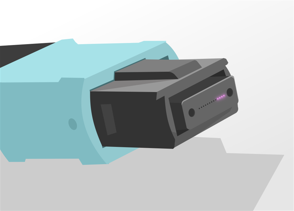
When dealing with QSFP 40G SR4 transceivers, take note that the connector isn't an LC type; instead, it's an MPO/MTP12 receptacle.
Additionally, you'll notice four small orange dots positioned in the center, between the two alignment pins. These dots serve as the entry and exit points for data (Rx/Tx) within the transceiver.
The space between these four dots remains unused, as it corresponds to unused fiber paths. The four Tx (transmit) and four Rx (receive) channels align with the outer fibers of an MTP cable.
When you face an SR4 QSFP or an MTP cable with their key side up, you'll consistently find that they receive on the left side (or your right when facing them) and send data on the right side (or your left when facing them).
You can think of it as a sort of "punch and receive" arrangement.
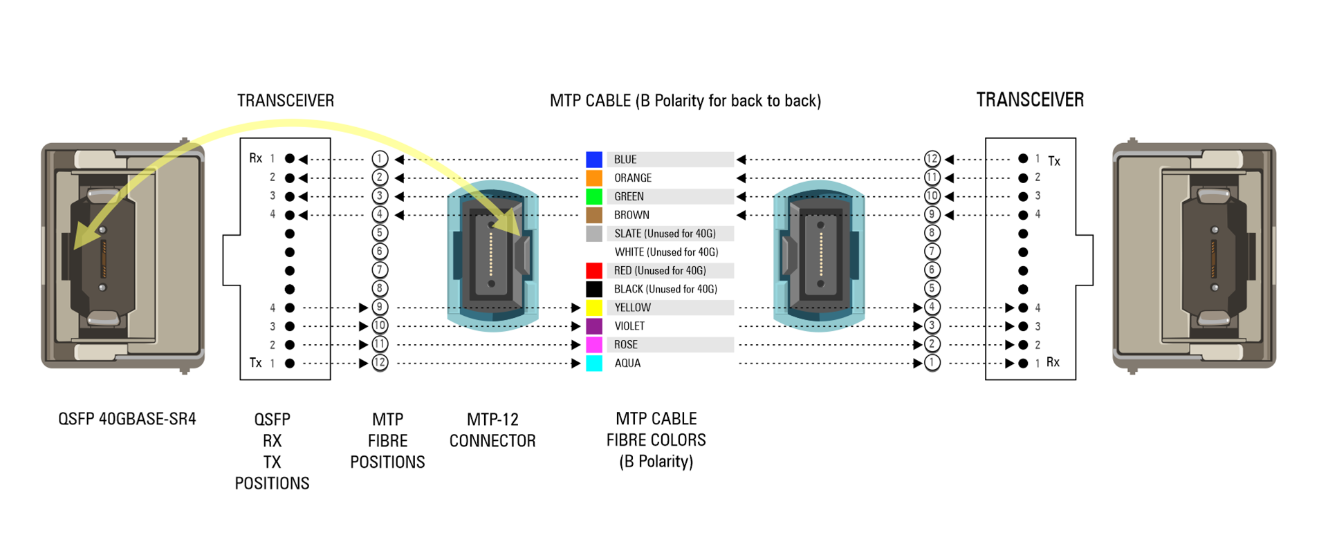
MTP12 cables are numbered from 1 to 12, but for 40G SR4, only eight of these positions are used:
4 Rx positions (cable positions 1 to 4)
4 Tx positions (cable positions 9 to 12) Positions 5 to 8 are not utilized by the QSFP transceiver.
It's worth noting that these unused positions don't need to carry any data signals, which can lead to cost savings in structured cabling. However, this deviates from the standard MTP12 cabling practice.
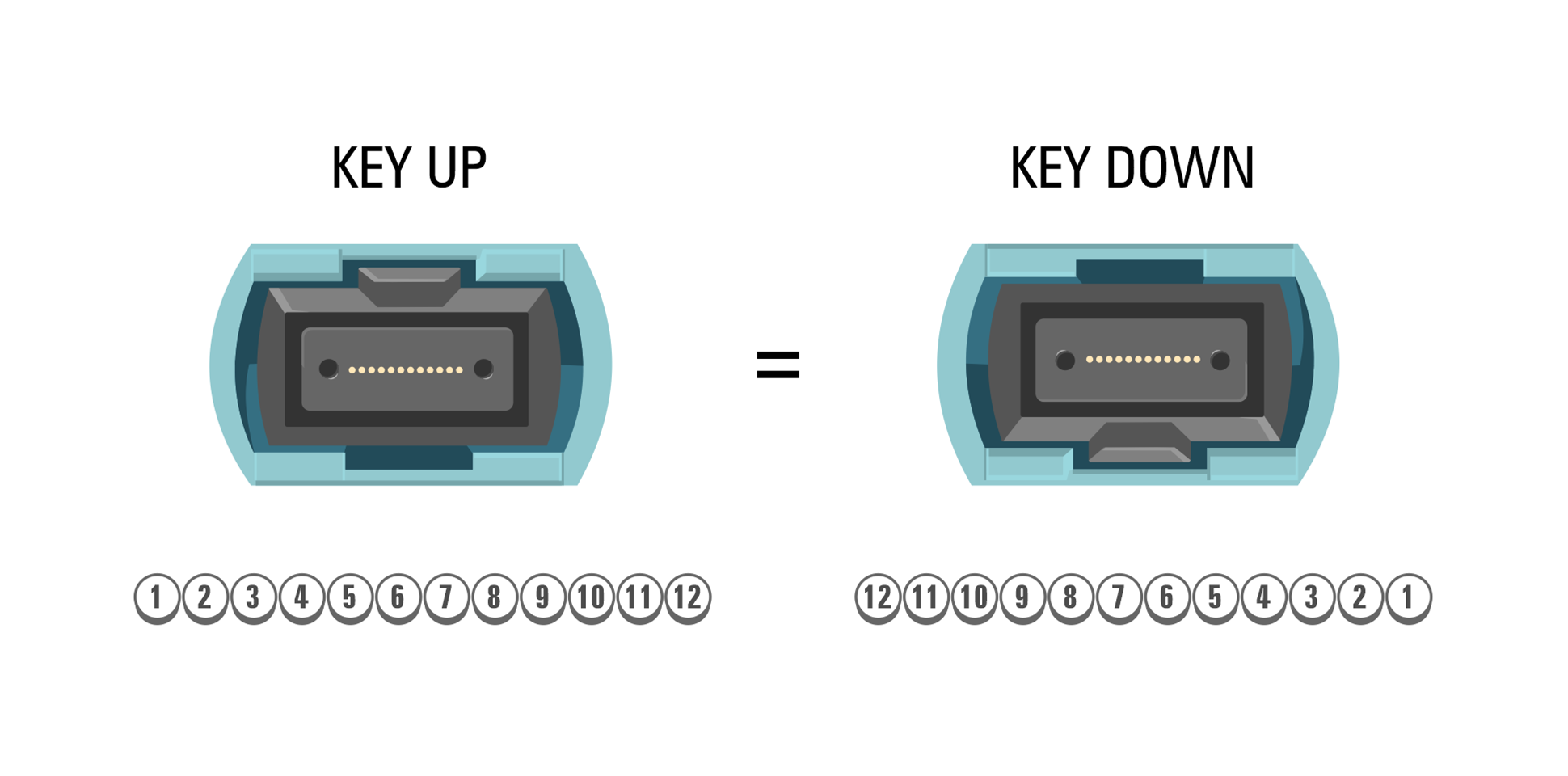
Regardless of the color of the fibers, the MTP12 positions are always arranged as follows:
Key side up
From left to right
Numbered from 1 to 12
This numbering scheme remains constant, irrespective of the fiber's color (e.g., position 1 might correspond to a blue or aqua-colored fiber).
Key Considerations
When selecting MTP cabling for 40G SR4 QSFPs, keep these points in mind:
QSFP Tx/Rx channels will always align with specific MTP positions, regardless of the cabling behind them.
Rx1 corresponds to position 1, Tx1 corresponds to position 12
Rx2 corresponds to position 2, Tx2 corresponds to position 11
Rx3 corresponds to position 3, Tx3 corresponds to position 10
Rx4 corresponds to position 4, Tx4 corresponds to position 9
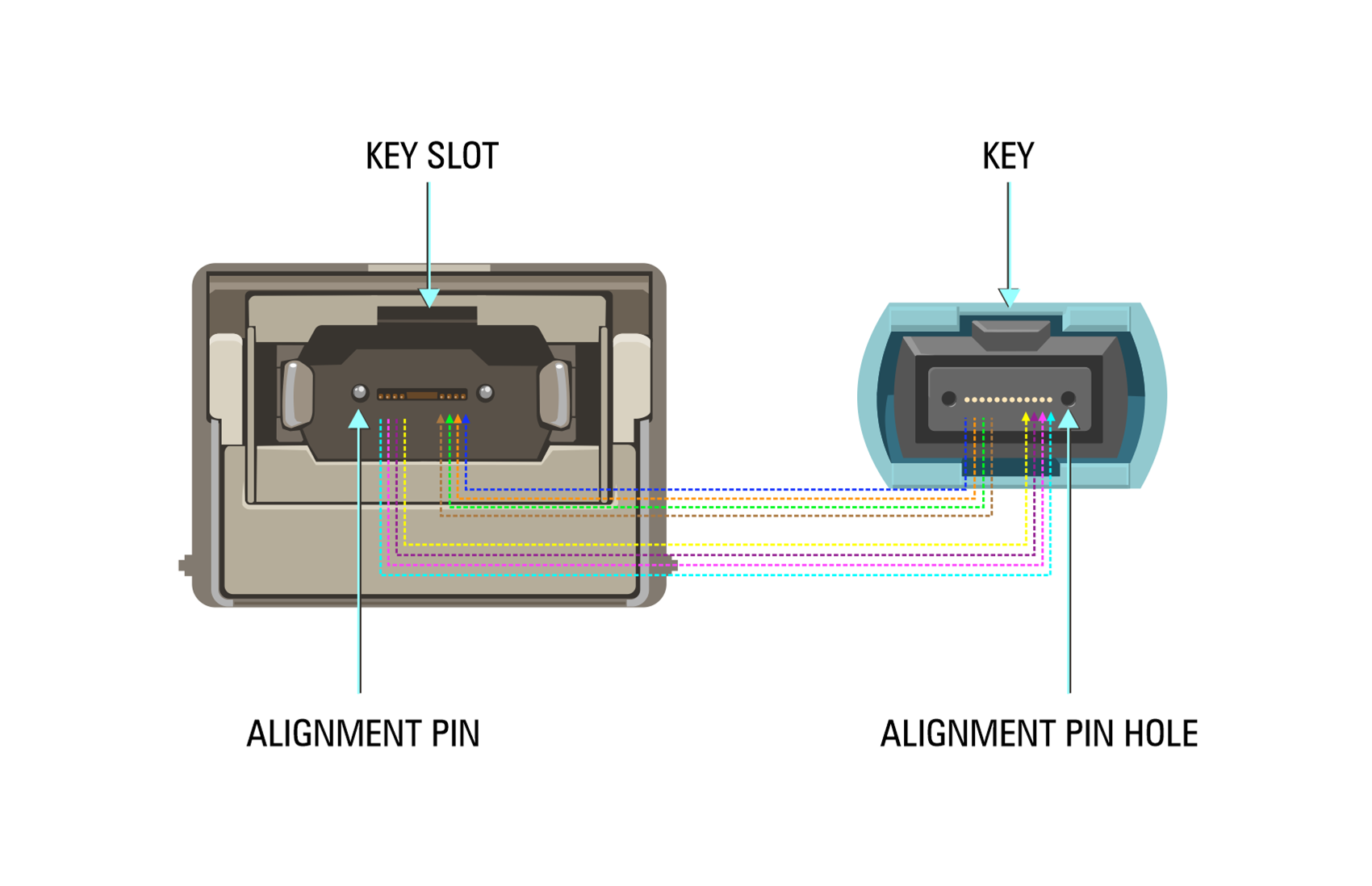
The MTP cable head should be female (with no alignment pins; it should have holes).
Alignment pins are located inside the QSFP.
Common Mistakes
Here are some common errors to avoid:
Polarity Mistake:
Using the wrong polarity (e.g., A instead of B) can cause light to exit the MTP cable in the wrong positions. This can result in light coming out of positions 9-12 instead of 1-4.
Typically, this mistake occurs when using an MTP cable with polarity A instead of the required polarity B for direct QSFP-to-QSFP connections.
When connecting devices via a patch panel, always confirm the required cable polarity with your patch panel vendor.
Incorrect Connector Gender:
The MTP cable should have a flat head with no protruding pins.
Alignment pins are located inside the QSFP, while the MTP connector features alignment holes.
Make sure you use the correct gender, which should be female.
Physical Appearance of 100GBASE-SR4 Transceiver
In addition to the SR4 transceiver's appearance mentioned above, the 100GBASE-SR4 version looks slightly different:
Instead of 12 tiny fiber links arranged in a row, it has four slightly larger holes (two on the left and two on the right).
Pairing Information
Pairing is particularly important in 10G mode. Pairs (Rx and TX) always share the same numbering:
Pair 1 is Rx1 + Tx1 (positions 1 and 12)
Pair 2 is Rx2 + Tx2 (positions 2 and 11)
Pair 3 is Rx3 + Tx3 (positions 3 and 10)
Pair 4 is Rx4 + Tx4 (positions 4 and 9)
For direct connections (back-to-back) using QSFP to QSFP MTP12 cabling without a patch panel or adapter, you should use:
Polarity B
Detailed cable specifications: EIA/TIA-604-05 (FOCIS-5) MTP-12 to MTP-12 cable
Female/female connectors
Polarity B (positions 1 to 12, key side up)
