

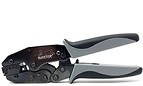
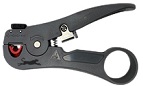
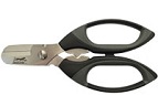
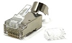
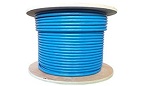
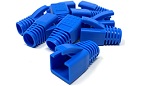
Essential Tools and Products Needed
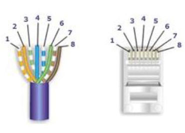
Wire Diagram for 568-B (Standard) Pinout
Pair # Wire
1 White / Blue
- White / Blue 5
- Blue / White 4
2 White / Orange
- White / Blue 1
- Orange / White 2
3 White / Green
- White / Green 3
- Green / White 6
4 White / Brown
- White / Brown 7
- Brown / White 8
1 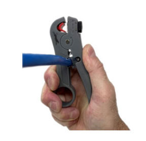
Create a clean cut on your cable
2 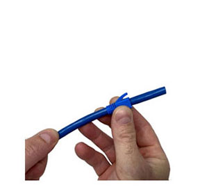
If using strain relief boots slip boot over outer jacket
3 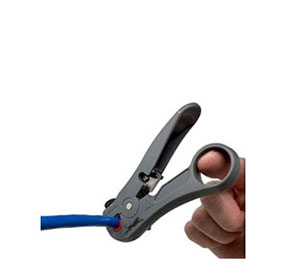
Strip cable about 1 ½” back on cable by placing cable stripper on cable and rotating it around the cable
4 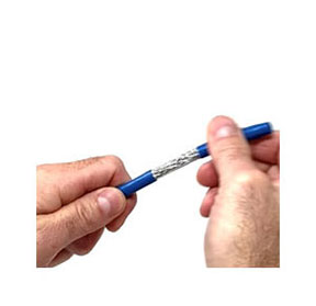
Twist off the outer jacket exposing the shielding & conductors
5 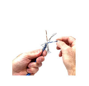
Peel away outer shielding, pair shielding, and untwist conductors
6 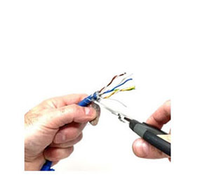
Cut away excess foil and shielding NOTE: Do not cut off drain wire
7 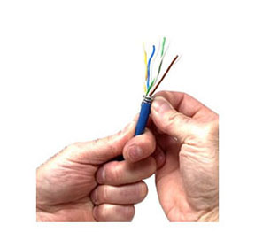
Wrap drain wire around top of cable jacket
8 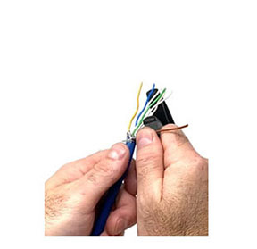
Align and straighten each conductor using a straight edge TIP: The handle of wire scissors works great.
9 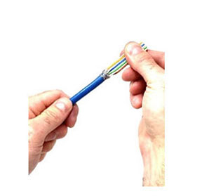
Tightly push together conductors while continuing to straighten conductors
10 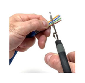
Cut conductors on angle 1” from cable jacket
11 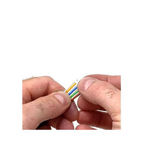
Slowly push load bar onto conductors making sure conductors align properly NOTE: Angle side of load bar will face non-tab side (bottom) of plug
12 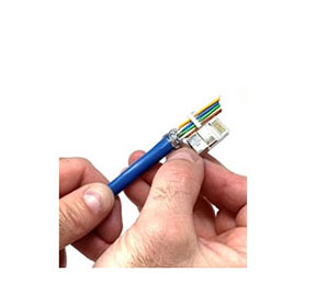
Using the plug for reference, mark where to cut conductors straight
13 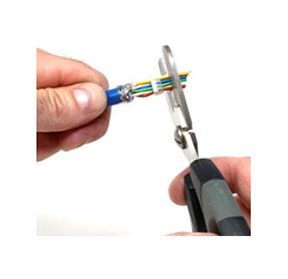
Provide a straight cut of conductors
14 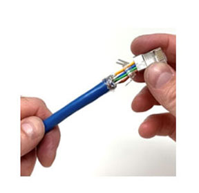
Push plug over conductors. NOTE: Angle side of load bar will face non-tab side (bottom) of plug
15 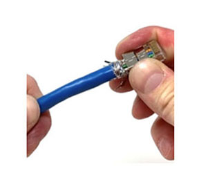
Push plug on, towards jacket until conductors slide into plug contacts.
17 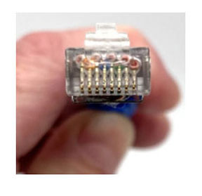
Visually check to make sure conductors properly alligned into plug
18 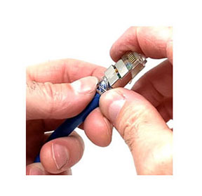
Wrap shielding clamp around cable jacket
19 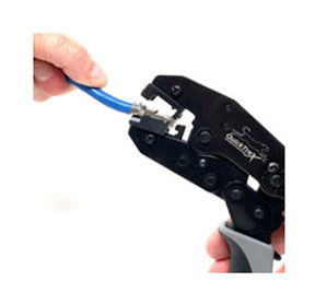
Place plug in crip tray tab down
20 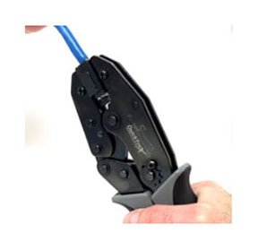
Squeeze handles together to crimp plug and cable/shield clamp
21 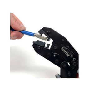
Crimper will automatically release once crimped. Then lift and remove plug from crimp tray.
22 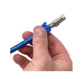
If using strain relief boots, slip boot up and over plug and tab util in proper position.
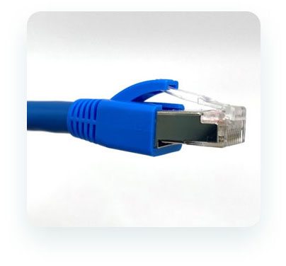
Completed Plug Installation with Strain Relief Boot