

In today’s demanding network world, using pre-terminated fiber saves significant time and delivers superior, consistent results compared to field terminations. To maximize these advantages, careful planning is essential.
This guide provides a practical, installer-focused framework—moving beyond theory to real-world application. We will walk you through the three crucial initial decisions:
- Fiber Type: Understanding the differences between OS1/OS2 Single-Mode and OM1–OM5 Multi-Mode.
- Connector Type: Choosing the best fit among LC, SC, and high-density MPO/MTP connectors.
- Assembly Type: Selecting the correct assembly for environments ranging from standard indoor to harsh, armored, or aerial installations.
Finally, we'll compare the pre-terminated and field-terminated approaches, detail the necessary testing and validation steps, and conclude with an Installer Best-Practice Checklist you can use immediately.
What Are Pre-Terminated Fiber Optic Assemblies? (Technical, Not Basic)
A pre-terminated fiber assembly is a complete, factory-engineered system designed for guaranteed performance and rapid deployment. Work shifts from uncertain field conditions to a controlled production process.
Factory-Built, Tested, and Certified
Each assembly is cut, polished, connectorized, and tested in a clean environment. Individual connectors undergo IL/RL testing, geometry checks, and automated inspection. QC documentation ensures compliance before the product ships.
Plug-and-Play for High-Density Rollouts
Fully finished and ready to install, these assemblies minimize labor and skill requirements. In dense environments like data centers, MPO/MTP systems enable quick deployment of many fibers at once, enhancing scalability.
Eliminating Field-Termination Risks
Factory assembly removes the common risks of field work—contamination, insertion loss variability, and polarity errors. This ensures certified optical performance and correct channel alignment upon arrival.
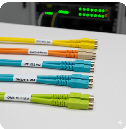
Fiber Type Selection: OS1/OS2 Singlemode Vs OM1–OM5 Multimode
Choosing the right fiber optic cable installation is one of the most important early decisions in any pre-terminated installation. Once selected, it defines your performance envelope—distance, bandwidth, scalability, and even the long-term cost of the network. In short: choose wisely now, so you don’t rebuild later.
Multimode Fiber Breakdown (OM1–OM5)
Multi-Mode Fiber (MMF) is built for short-reach, high-bandwidth runs inside buildings, data halls, and campus environments. With its larger core, it carries multiple light modes simultaneously. Here’s a quick, clean comparison of the MMF family:
Multi-Mode Generations at a Glance
|
Type |
Core Size |
Jacket Color |
Typical Use |
Performance Notes |
|---|---|---|---|---|
|
OM1 |
62.5 µm |
Orange |
Legacy building networks |
1 Gb/s up to ~275 m; not suitable for modern 10G+ workloads |
|
OM2 |
50 µm |
Older campus/building links |
Supports 1 Gb/s up to 550 m; still not ideal for 10G+ |
|
|
OM3 |
Aqua |
Data centers |
Laser-optimized; 10G up to 300 m; supports 40/100G |
|
|
OM4 |
High-density data centers |
10G up to 550 m; improved reach for 40/100G |
||
|
OM5 |
Lime Green/Aqua tone |
SWDM-enabled environments |
Supports multi-wavelength 850–950 nm; enables cost-efficient 100G–400G over fewer fibers |
Quick note: OM1/OM2 multimode fiber optic cables are now considered legacy. OM3/OM4 remain the mainstream choice, while OM5 is gaining traction in SWDM applications.
Singlemode Fiber (OS1/OS2)
Single-mode Fiber (SMF) uses a narrow core that carries a single light mode—meaning virtually no modal dispersion and extremely long reach. It’s the go-to choice for service providers, long-haul networks, and any installation where distance or precision is non-negotiable.
OS1 vs OS2 Summary
|
Type |
Typical Use |
Distance Capability |
Key Advantage |
|---|---|---|---|
|
OS1 |
Indoor/campus long-reach |
Up to ~10 km |
Good for controlled indoor environments |
|
OS2 |
Outdoor, metro, long-haul |
80–120 km+ (with proper optics) |
Low-loss standard for modern long-distance links |
Key note: OS2 single mode fiber optic cable is the modern default for any long-reach or future-proof build.
Which Fiber Type Should You Choose for Pre-Terminated Systems?
The decision typically comes down to two factors: distance and total cost of ownership (including optics).
Choose Multi-Mode (OM3/OM4) If:
- Your links are under 550 meters.
- You are working inside a data center or building.
- You want lower-cost optics for 10G/40G/100G.
- You only need moderate future scalability.
OM3 Vs OM4?
When you want extra reach and smoother performance at 10G and above, OM4 is a practical step-up for a minimal premium.
Choose Singlemode (OS2) If:
- Your runs exceed 550 meters.
- You want maximum scalability (10G → 400G → 800G and beyond).
- You’re connecting buildings, campuses, or outdoor spans.
- You want a fiber plant that won’t need replacing for decades
OS2 Vs OM4?
For shorter distances on a limited budget, OM4 multimode fiber optic cable is perfectly fine. But if you want something that will stay relevant for decades, OS2 single mode fiber optic cable is the clear choice—particularly in pre-terminated builds where you only get one shot at selecting the right fiber.
Connector Selection for Pre-Terminated Fiber (LC, SC, MPO/MTP)
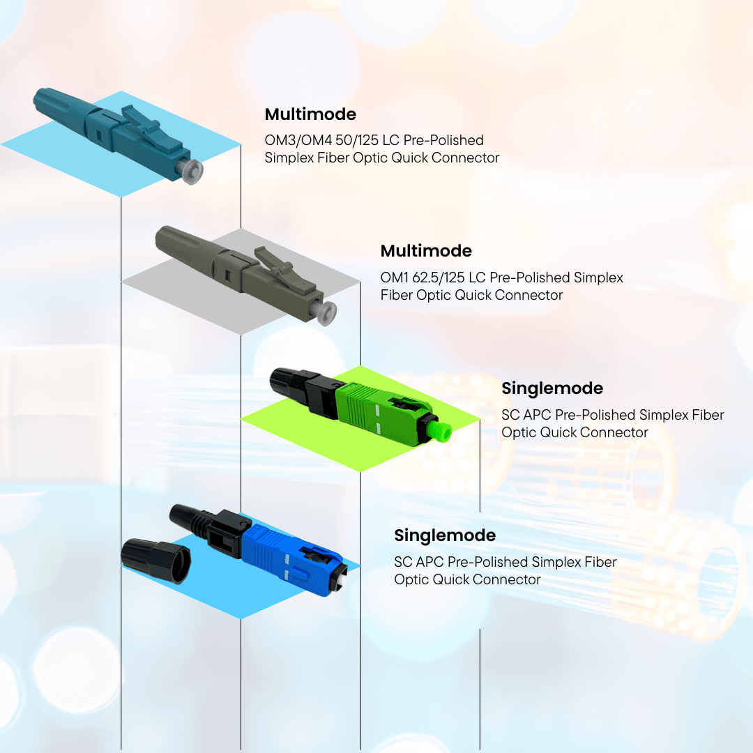
In any pre-terminated build, the fiber optic cable connector is the interface that makes the entire system work. The type you choose affects density, performance, workflow efficiency, and even how much room you have left in your racks. So, this decision isn’t just about matching ports—it’s about choosing the connector that best supports the environment you’re building for.
LC Connectors — The High-Density Standard
The LC fiber optic connector, featuring a compact 1.25 mm ceramic ferrule, has become the default choice in modern data centers. Its smaller design provides twice the port density of older connectors, making it perfect for crowded racks and high-capacity switching environments.
LC Variants Overview
|
LC Type |
Polish |
Typical Use |
Key Advantage |
|---|---|---|---|
|
LC/UPC |
Ultra Physical Contact |
Most digital systems (SM/MM) |
Low insertion loss; standard for data centers |
|
LC/APC |
Angled (8°) Physical Contact |
RF video, FTTx, PON |
Minimizes back-reflection; essential for precision optical links |
Key Insight: If your priority is maximizing ports in a switch or patch panel, LC is almost always the right call.
SC Connectors - Reliable for Legacy & Conversion Networks
The SC fiber optic connector, featuring a durable push-pull design and a 2.5mm ceramic ferrule, was the industry standard for many years. While its larger size limits its use in today's high-density switching environments, it remains a reliable choice for building backbones and legacy networks where space is not a concern.
LC vs SC at a Glance
|
Feature |
LC |
SC |
|---|---|---|
|
Size / Density |
Very high |
Moderate |
|
Typical Use |
Data centers, high-density racks |
Legacy networks, building backbones |
|
Strength |
Maximum port count |
Robust, cost-effective |
|
Best For |
Modern SM/MM deployments |
Older gear or conversions |
Key Consideration: SC is still a dependable and affordable option when upgrading older systems or connecting to equipment that requires SC connectors.
MPO/MTP - High-Fiber Count for Parallel Optics
For true high-density performance, MPO/MTP connectors are unmatched. These multi-fiber interfaces (12, 24, 32 fibers and beyond) enable plug-and-play deployment of 40G, 100G, and 400G links - often with a single connection.
Key Planning Factors for MPO/MTP Trunks
|
Consideration |
What It Means |
Why It Matters |
|---|---|---|
|
Polarity (A, B, C) |
Ensures TX → RX alignment |
Prevents cross-over, maintains correct signal flow |
|
Gender (Male/Female) |
Pins vs no pins |
Connectors must be paired correctly end-to-end |
|
Polish (UPC/APC) |
End-face type |
UPC for data centers; APC for reflection-sensitive systems |
Key Note: MPO/MTP is your go-to option for high-bandwidth backbones or anywhere you plan to scale quickly.
Choosing the Right Connector for Your Deployment
Your connector choice should align with your physical infrastructure, equipment interfaces, and long-term network plan.
- Choose LC: When density matters and you want maximum ports in switches and panels.
- Choose SC: When connecting to legacy systems or when space constraints are minimal.
- Choose MPO/MTP: For backbone aggregation, parallel optics, and any environment pushing 40G/100G/400G with fast, scalable installation.
Key Insight: In pre-terminated systems—where the physical layer is fixed from the start—getting the connector decision right ensures your deployment is both efficient today and ready for whatever speed upgrades come next.

I see two recurring mistakes in connector selection: deploying costly MPO where a simple LC duplex is all that’s needed, and forcing LC where parallel optics demand MPO. The guideline is straightforward—use LC/SC for client interfaces and point-to-point links, and reserve MPO for structured backbones and high-density parallel optics. Making the right choice early prevents expensive panel rework and eliminates future bottlenecks.
Tom Damiano
Fiber Optic Specialist
Assembly Types: Indoor, Outdoor, Harsh-Environment, Armored & Aerial
For more than 25 years, we have specialized in custom pre-terminated fiber assemblies built to exact project requirements. Every assembly—spanning all jacket types, fiber types, and connector options—is manufactured in the USA by trained technicians and shipped with certified test results. Our team can match the precise jacket and connector specifications required for your environment, even for unique configurations.
Pre-terminated assemblies can be ordered in indoor (plenum), indoor/outdoor, tactical, or outdoor variations, available in non-armored or armored designs. We support strand counts from 2, 4, 6, 12, 24 all the way up to 288 in both Multimode (OM1–OM5) and Singlemode fiber cores. Selecting the right cable type is essential for long-term durability, and our Easy Configurator Builder Tools make customization simple.
Outdoor Ruggedized Assemblies: These assemblies use UV-resistant PE jackets and moisture-blocking elements to resist weather, sunlight, and environmental stress.
Direct-Burial and Armored Options: The outdoor armored direct burial (OSPDB) fiber optic cable has a heavy-duty polyethylene (PE) UV and waterproof jacket, corrugated steel tubing, and water-blocking swellable tape surrounding the fiber optic strands.
Harsh-Environment and Industrial Assemblies:
We offer specialized pre-terminated fiber optic cable assemblies engineered for resilience and reliable deployment in challenging environments.
- Outdoor (OSP) Aerial Assemblies: These assemblies are rated for nearly all outdoor applications, ideal for aerial installations along utility poles without the need for cable lashing. They utilize a Figure 8 configuration, which consists of the messenger, the webbing, and the fiber optic cable itself.
- Tactical Fiber Assemblies: Our tactical assemblies include super-strong, abrasion and UV-resistant Tech Flex protective sleeves on both ends that easily fold back to expose the connectors. The sleeves are securely attached using glue-set heat shrink and high-quality adhesive. Assemblies use 3 mm polyurethane furcation tubing with Kevlar and sequential labeling.
Indoor/Plenum/Riser Assemblies use tight-buffered constructions with fire-rated jackets suitable for building pathways:
- Plenum (CMP): For air-handling spaces such as drop ceilings and raised floors; uses low-smoke, zero-halogen materials.
- Riser (CMR): For vertical runs between floors within building shafts.
Indoor/outdoor rated cables add versatility by meeting both exterior durability requirements and interior flame ratings, eliminating the need for a transition splice at building entry.
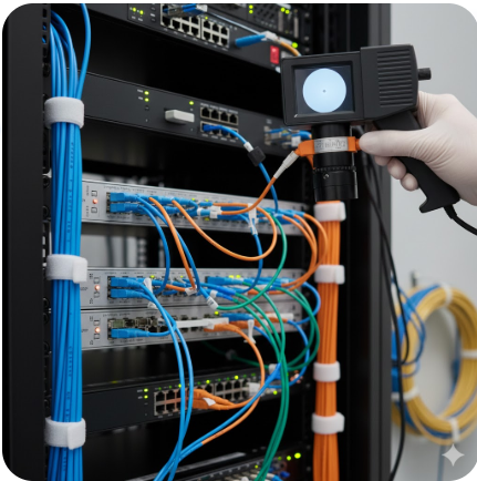
Testing & Validation for Pre-Terminated Fiber Installations
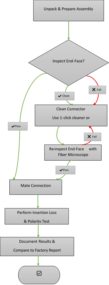
While pre-terminated fiber arrives with factory certification, the final responsibility for a flawless network lies with the installer. A rigorous validation process on-site is non-negotiable to ensure the system performs as designed. This process confirms the integrity of the installation itself, safeguarding your investment. The entire procedure can be summarized by a core, repeatable cycle: Inspect → Clean → Test → Document.
The workflow provides a step-by-step guide to executing this cycle effectively, ensuring no critical step is missed.
Required Inspection Steps (Before, During, After)
As illustrated in the workflow, a successful installation follows a strict, repeatable process:
- Before (Inspect): Visually inspect every connector end-face with a microscope for shipping damage or contamination. This is the first and most critical decision point in the workflow.
- During (Clean): If inspection fails, immediately clean any contaminated connectors using approved tools and techniques before making any connection. The loop back to re-inspection is mandatory.
- After (Test & Document): Only after a clean inspection should you mate the connection, test each link for insertion loss and polarity, and then document the results against the baseline factory test report.
Insertion Loss, Polarity, and Endface Validation
The “Test” phase validates installation across three critical areas:
- Insertion Loss: Measure total channel loss using an LSPM or OLTS to ensure compliance with fiber type standards and system budget.
- Polarity: Verify correct Tx‑to‑Rx alignment in duplex and MPO systems for proper signal routing.
- Endface Validation: Conduct a final fiber scope inspection to confirm connectors remain contamination‑free after installation.
Cleaning Requirements and Tool Recommendations
Contamination is the leading cause of fiber failure. A “clean-first” approach is essential, supported by the right tools:
- For Inspection: Use a handheld fiber scope to detect microscopic contaminants.
- For Cleaning:
- Lint‑free wipes with fiber‑optic solvent for bulkhead and connector cleaning.
- 1‑click cleaners for fast, effective cleaning of both ferrule and mating sleeve.
Following this disciplined workflow ensures the guaranteed performance of your pre‑terminated fiber is achieved in the live installation.
Installer Best-Practice Checklist
A successful pre-terminated fiber installation is built on meticulous planning and execution. Use this concise, 10-point checklist as your definitive guide to ensure a flawless deployment from start to finish.
Complete 10-Point Checklist
Phase 1: Pre-Order & Planning
- Validate Fiber Type: Confirm the correct fiber (OM3, OM4, OM5 for multi-mode; OS2 for single-mode) based on distance and bandwidth needs, as defined by TIA-492 & ISO/IEC standards.
- Confirm Connector Requirements: Specify LC, SC, or MPO/MTP connectors, ensuring hardware compatibility as per TIA-604 (FOCIS) connector standards.
- Verify Cable Length & Slack: Measure the exact pathway length and include planned slack for service loops (typically 10-15 feet).
- Check Bend Radius & Pathway: Ensure pathways and conduits can accommodate the cable without violating its minimum bend radius.
- Confirm Environment Type: Select the appropriate jacket rating (Indoor, Plenum, Riser, Outdoor) for the installation environment.
- Verify Armored vs. Non-Armored: Choose an armored fiber optic cable for direct burial, rodent-prone areas, or harsh environments where crush resistance is critical.
Phase 2: Installation & Validation
- Inspect & Clean Connectors: Before routing the cable, inspect every connector end-face with a fiber microscope and clean thoroughly if contaminated.
- Validate MPO Polarity & Gender: For MPO systems, confirm the polarity method (A, B, C) and that the connector gender (male with pins, female without) is correct for a proper mate.
- Perform IL/OL Testing: After installation, use a light source and power meter (LSPM) to test Insertion Loss (IL), ensuring it is within the system's loss budget as per TIA-568 field testing guidelines.
- Document Results: Record all test results, serial numbers, and port assignments. Compare on-site data with the factory test report for a complete project file.
Summary & Next Steps
Pre-terminated fiber optic systems represent a fundamental shift towards smarter, more efficient network infrastructure. By moving the complex termination process to a controlled factory environment, they deliver unmatched advantages: guaranteed performance, dramatically reduced installation time, and the elimination of field-termination errors. From selecting the right fiber type and ruggedized assembly to following a disciplined validation workflow, this framework empowers you to leverage these benefits with confidence on your next project.
Let our specialists match you with the optimal pre-terminated assembly for long-term performance
Frequently Asked Questions (FAQ)
Q1. What is the main technical advantage of pre-terminated fiber over field termination?
Pre-terminated fiber guarantees certified optical performance from the factory, eliminating the variability, contamination risks, and human error associated with field termination.
Q2. How does choosing OS2 single-mode vs. OM4 multi-mode affect long-term scalability?
OS2 single-mode supports next-generation speeds over long distances, ensuring unlimited scalability for future upgrades. OM4 multi-mode is limited by distance and bandwidth, which can restrict long-term network growth.
Q3. When is an MPO/MTP connector required, and what configuration issues must installers avoid?
MPO/MTP connectors are required for high-speed parallel optics (40G, 100G, 400G). To avoid link failure, installers must ensure proper polarity (consistent Method A/B/C) and correct gender pairing (male-to-female) throughout the channel.
Q4. What is the most critical step in validating a pre-terminated fiber link on-site?
The most critical step is visual inspection and cleaning of each connector before mating. Even factory-fresh connectors can be contaminated during handling, which can cause immediate performance loss or failure.
Q5. For a high-density data center backbone, is OS2 LC duplex or OM4 MPO the better pre-terminated choice?
For high-density data centers, OS2 with MPO/MTP is the better long-term choice. It supports future speeds (400G+) over distance and provides modular density, while OM4 MPO is limited to short-reach applications.