

Due to an overwhelming response to our category 5 & 6 tutorial, and many requests for information and wiring diagrams of "straight through" and "crossover" (cross-pinned) patch cords, we have made this informational page and technical video. On this page, we will cover making patch cords, and other technical and non-technical issues relating to category 5 and 6 patching and connectivity from device to device. Below, you will find the diagrams for 568A, 568B, and crossover patch cables. We suggest that you read on, past the diagrams for some very useful and important information.
As always, there continues to be Controversies over standards and practices regarding the use and making of patch cords, and UTP cable in general. Please see our section below titled: "Controversies and Caveats : Category 5, 5E, and Cat 6 Patch Cables". We hope that you will find it interesting and informative.
568-B Wiring
| Pair # | Wire | Pin # |
|---|---|---|
|
1White / Blue
|
White / Blue | 5 |
| 4 | ||
|
2White / Orange
|
White / Orange | 1 |
| 2 | ||
|
3White / Green
|
White / Green | 3 |
| 6 | ||
|
4White / Brown
|
White / Brown | 7 |
| 8 |
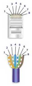
568-A Wiring
| Pair # | Wire | Pin # |
|---|---|---|
|
1White / Blue
|
White / | 5 |
| 4 | ||
|
2 White / Orange
|
White / Orange | 1 |
| 2 | ||
|
3White / Green
|
White / Green | 3 |
| 6 | ||
|
4White / Brown
|
White / Brown | 7 |
| 8 |
 Notes for wiring diagrams above
- For patch cables, 568-B wiring is by far, the most common method.
- There is no difference in connectivity between 568B and 568A cables. Either wiring should work fine on any system*. (*see notes below)
- For a straight through cable, wire both ends identical.
- For a crossover cable, wire one end 568A and the other end 568B.
- Do not confuse pair numbers with pin numbers. A pair number is used for reference only (eg: 10BaseT Ethernet uses pairs 2 & 3). The pin numbers indicate actual physical
- locations on the plug and jack.
1 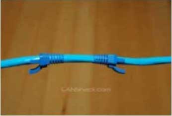
Cut the cable to the length that you will need. If you are planning to use boots, this would be a good time to slip them on. Place each boot facing out on the cable. |
2 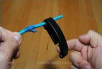
Skin the cable about 1.5down. For fast and dependable skinning we recommend our QuickTreX™ EZ Cable stripper. |
3 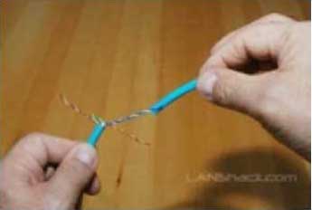
Remove all of the twists in the cables pairs. TECH-TIP: Use a piece of the removed insulation to make it easy to remove the twists from each pair. Un-twist each pair, and straighten each wire between the fingers. |
4 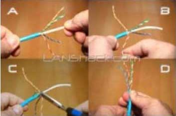
Cat 6 cable has a center spine that needs to be removed. Pull on the spine and fold the pairs back. Then cut the spine as close to the cables end as possible. |
5 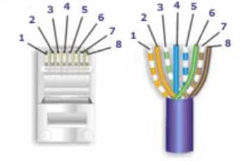
Place the wires in the order of one of the two diagrams shown above (568B or 568A). Here we have chosen the 568B diagram which is by far the most popular. If you are unsure, go with the 568B wiring. |
6 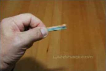
Bring all of the wires together, until they touch. Hold the grouped (and sorted) wires together tightly, between the thumb, and the forefinger. At this point, recheck the wiring sequence with the diagram. |
7 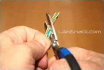
TECH-TIP: Cut the wires on a very sharp angle to make it easier to install the load-bar(in the next step). |
8 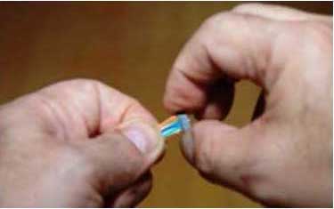
Insert the loadbar on the wires one wire at a time. This is why we recommended cutting the wires on an angle. |
9 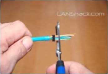
Check the wiring sequence one more time. Than slide the load bar down all the way and make a straight cut about 0.25 past the loadbar. A perfectly straight cut is essential here. That is why we strongly recommend our new QuickTreX™ Wire Surgeon Electricians Scissors. |
10 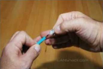
Insert the connector onto the load bar assembly. Hold the plug with the copper connectors up and the locking clip facing down. In this configuration, the Brown Pair of wires should be to the right side |
11 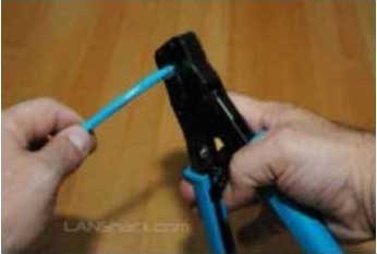
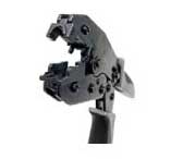
For Crimping we recommend our QuickTreX™ Ratchet Crimper for RJ-45 and RJ-11/12.. Push the connector all of the way in and then squeeze down all the way on the crimper. Remove the connector from the crimper body. |
12 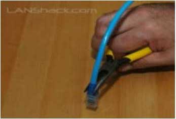
Slide the boots (if used) all the way up to the connector. If necessary, use a tapping motion as shown in the illustration. |
| 13
Repeat the procedure on the other end of the cable using the same wiring diagram. |
14 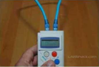
Test the cable using a high quality four pair tester. For this we recommend our LANTEST-PRO Cable Tester. |
Patch Cable Assembly Instructions
Below are the steps outlined in the video.
Once you get good at it, with some dexterity the assembly time will be less than a minute.Notes Regarding Making Category 6 Patch Cable:
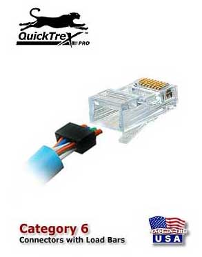
- The RJ-45 plugs are normally made for either solid conductors or stranded conductors. It is very important to be sure that the plug that you use matches the conductor type. It is extremely difficult to tell the difference between the two by looking at them. When you buy these plugs, be sure to categorize, and store them carefully. Using the wrong type can cause intermittent problems. The QuickTreX™ Category 5E, 8 Conductor Modular Plugs , OR QuickTreX™ Category 6, 8 Conductor Modular Plugs that we sell are rated for both Solid and Stranded cable.
- Ordinarily, it would be taboo to untwist the pairs of any category 5 or 6 cable. The one exception to this rule is when crimping on RJ-45 plugs. It would be impossible to insert the wires into the channels without first untwisting and straightening them. Be sure not to extend the un-twisting, past the skin point. If you do it properly, you will wind up with no more than 1/2" of untwisted conductors (up to 1/2" of untwist meets the cat 5 or 6 specification).
- If the completed assembly does not pass continuity, you may have a problem in one, or both ends. First try giving each end another crimp. If that does not work, then carefully examine each end. Are the wires in the proper order? Do all of the wires fully extend to the end of the connector? Are all of the pins pushed down fully. Cut off the suspected bad connector, and re-terminate it. If you still have a problem, then repeat the process, this time giving more scrutiny to the end that was not replaced.
It is now not only possible but also easy to field terminate Category 6 modular plugs thanks to the new QuickTreX™ Category 6 modular plug which contains a new Patented Conductive NEXT Reduction System. The Conductor Loading Bar is molded from a material that substantially reduces the affect of NEXT within the Plug Body. The conductors are isolated by plastic that absorbs the NEXT from between the conductors and channels it away so that the Plug can perform to Category 6 levels. When assembled onto Category 6 compliant patch cable it will pass all TIA/EIA requirements for NEXT and Return Loss. This will help your Category 6 channel maintain increased headroom to assure your network operates at its best.
Controversies and Caveats: Category 5, 5E, and Cat 6 Patch Cables
568B vs. 568A
For patch cables, 568-B wiring is by far, the most common wiring method. Virtually all pre-assembled patch cables are wired to the B standard. There is no difference in connectivity between 568B and 568A cables. Therefore, a 568B patch cable should work fine on a 568A cabling system, and visa-versa.
Re-use of old cables
We have seen this happen time and time again. Perfectly good patch cables that have been working fine for years, get removed from their installation, and re-installed on the same, or different network. The result can be a nightmare. What happens is that the cable, over time, adapts to the way that it is bent in it's original installation. When these cables are removed and re-installed, they can either completely lose their connection, or develop intermittent problems. This is due to stresses that may be opposite to what they were originally subject to. If the integrity of your network is more valuable than the price of new patch cables, then we strongly suggest that you use brand new cables for all closet cleanups, network moves, etc.
Stranded vs. Solid wire
Almost all patch cables that are made have stranded wire. Stranded wire is normally specified for use in patch cables due to its superior flexibility. There has been some talk recently, in the technical sector of the structured wiring community, regarding the possible use of solid conductors for patch cables. The reason for the spotlight on solid wire is that it is supposedly more stable, under a variety of conditions. Please note that we now offer custom Solid copper category 5E patch cables in Plenum insulation in lengths of up to 295 feet. These cables are suitable for use in air handling (Plenum) ceilings and environments.