

Introduction
Is your data center’s physical layer becoming a bottleneck for AI and cloud workloads?
You are not alone. As data traffic accelerates, many network managers are discovering that traditional duplex fiber can no longer keep pace—leading to rising complexity, higher costs, and major scalability challenges.
If you’re planning an upgrade or new deployment, you’re likely facing several familiar pain points:
- The Density Crunch: Racks are already at capacity, yet leadership expects support for more GPUs and higher bandwidth. How do you add 400G/800G ports without expanding your physical footprint?
- Cabling Complexity: Managing hundreds of LC duplex connections in modern spine-leaf designs is labor-intensive and error-prone. Every manual patch becomes a potential failure point.
- Future-Readiness Concerns: Will your current fiber plant support a smooth migration to 800G or 1.6T, or will it force an expensive, disruptive overhaul in a year or two?
- Signal Integrity Risks: At 400G and higher, there is virtually no margin for error. A tiny particle of dust or slight misalignment—insignificant at 10G can now disrupt multiple links and jeopardize critical AI workloads.
If these challenges sound familiar, this blog will walk you through the shift to multi-fiber solutions and show you how to choose the right MTP/MPO configuration to build a network that is faster, cleaner, more scalable, and fully prepared for tomorrow’s demands.
Why 400G/800G Demands Smarter Connectivity?
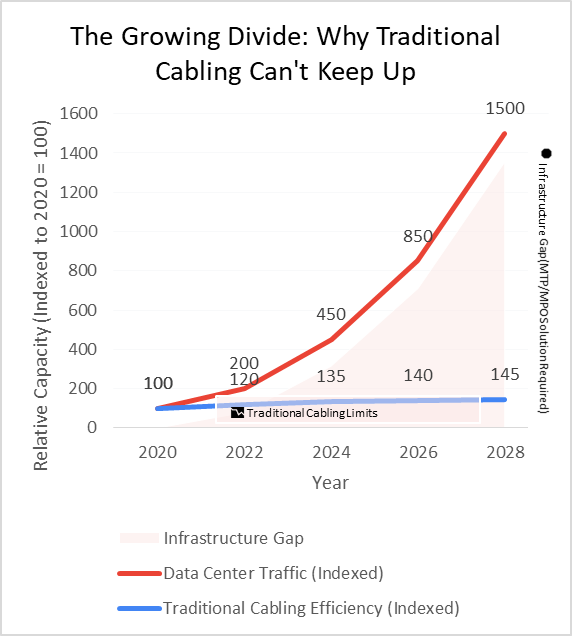 The drive toward 400G and 800G isn't just about keeping up with trends; it's a fundamental response to unprecedented demand. AI clusters, hyperscale cloud computing, and real-time analytics are generating data volumes that legacy 100G systems simply cannot handle efficiently.
According to a Dell'Oro Group report, the demand for 400G and 800G ports in data center switches is projected to grow at a CAGR of over 30% through 2027, driven largely by front-end AI and ML workloads. This isn't a gradual evolution—it's a step-change.
The core of this shift, as defined by standards like IEEE 802.3bs, is a move from serial to parallel optics. Instead of pushing more data down a single pair of fibers, parallel optics uses multiple fibers simultaneously to achieve breathtaking speeds. This fundamental change in how data moves is what makes your choice of physical infrastructure more critical than ever.
The Solution Shift: Embracing Multi-Fiber Trunk Architecture
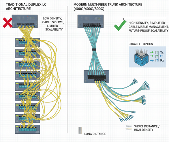
This is where MTP/MPO multi-fiber connectivity comes in. To overcome the limitations of duplex cabling, the industry has standardized on a trunk-based architecture built around these high-density connectors.
Parallel optics allows multiple fibers to transmit and receive data at the same time, dramatically increasing total bandwidth in a single, streamlined cable.
These trunk cables, available in both singlemode (for long-haul) and multimode (for data centers) versions, form the robust backbone of modern high-performance networks.
Choosing the Right MTP/MPO Solution for Your Environment
Selecting the correct configuration is essential to maintain signal integrity and ensure scalability. Here’s a breakdown of the key considerations.
Cable Type: Singlemode vs. Multimode
Singlemode MTP/MPO Trunks: These are designed for long-distance, high-speed links and are available in indoor, indoor/outdoor, Micro Armor and loose-tube jacket options. Fiber counts range from 12 (1×12) up to 288 (12×24), making them suitable for telecom providers and backbone networks.
Key Characteristics of Singlemode MTP/MPO Trunks
- Optimized for long-haul and backbone communication.
- Support transmission from 1Gbps to 400G+ over distances exceeding 100 km.
- Feature an 8–10 µm core that eliminates modal dispersion.
- Operate at 1310 nm and 1550 nm using DFB lasers.
- Commonly found in FTTH, long-haul networking, and high-speed interconnects.
Multimode MTP/MPO Trunks (OM3/OM4/OM5): This category of trunks available as OM3 and OM4—are preferred for shorter-range, high-density deployments such as enterprise data centers. They come in a variety of jacket types and can be customized in lengths up to 5000 feet with multiple strand configurations (1x12, 1x24, 4x12, 2x24, and more).
Key Features of OM3 MTP/MPO Trunks
- Laser-optimized multimode fiber for high-speed indoor traffic.
- Supports 10G up to 300 m, 40G up to 100 m, and 100G up to 70 m.
- Operates at 850 nm using VCSEL lasers.
- 50 µm core with 2000 MHz·km bandwidth.
- Widely used with MTP/MPO connectors in parallel optics.
Key Features of OM4 MTP/MPO Trunks
- Enhanced multimode fiber for ultra-high performance.
- Supports 10G up to 550 m, 40G up to 150 m, and 100G up to 150 m.
- Operates at 850 nm with improved bandwidth of 4700 MHz·km.
- Ideal for dense, high-performance data center environments.
Choosing the Right MTP/MPO Configuration
As networks migrate toward 400G and 800G, selecting the correct MTP/MPO cable configuration becomes critical to maintain signal integrity and scalability. A single misstep in configuration can result in polarity mismatches, excessive insertion loss, or future upgrade limitations.
Configuration Types: Trunk vs. Breakout
Network architects must first determine the functional role of the cable within the infrastructure:
- MTP/MPO Trunk Cables: Serve as the fiber backbone, typically linking patch panels, distribution frames, or main interconnects. These assemblies have MTP/MPO connectors on both ends and are optimized for high-density, permanent rack-to-rack or zone-to-zone connections.
- MTP/MPO Breakout Cables: Enable port fan-out or aggregation, converting a high-speed optical interface into multiple lower-speed channels. For instance, an MPO to LC breakout cable can split a 100G QSFP port into ten 10G LC connections, maximizing equipment utilization and port flexibility.
Polarity and Fiber Variants
Polarity ensures that the transmit (Tx) fibers align correctly with the receive (Rx) fibers end-to-end. Among the three standard polarity types—A, B, and C. Type B (flipped) is the most common choice for spine-and-leaf data center architectures, especially in parallel optics environments.
Fiber counts are generally based on 12-fiber increments (12, 24, 48).
- The 12-fiber MTP/MPO remains the industry standard.
- The 24-fiber MTP/MPO is increasingly preferred in AI-ready, high-density data centers due to its ability to reduce cabling complexity and support future 800G deployments, despite operating within a tighter loss budget.
Configuration Summary
|
Configuration Type |
Application Scenario |
Common Polarity Type |
Typical Fiber Count |
Connector Interface |
Use Case |
|
Trunk Cable |
Permanent rack-to-rack, spine-to-leaf, or zone backbone connections providing the core fiber pathway |
Type A or Type C |
12 or 24 fibers |
MTP/MPO ⇔ MTP/MPO |
High-speed backbone or inter-rack link in data center core/distribution layers |
|---|---|---|---|---|---|
|
Breakout Cable |
Switch-to-server fan-out, TOR (Top of Rack) aggregation, or test environments where ports are divided into multiple channels |
Type B (MPO to LC) |
8-fiber MPO ⇔ 4 LC |
MTP/MPO ⇔ LC duplex |
400G to 4×100G or 100G to 10×10G fan-out connections |

The precision of your components has a direct and measurable impact on your loss budget. While generic MPO connectors may be acceptable for lower data rates, Elite MTP® connectors are engineered with Ultra-Low-Loss (ULL) tolerances of ≤0.15 dB—performance that is essential for maintaining error-free transmission at 400G and 800G. The rigorous testing and validation behind this performance are documented in our MTP/MPO Insertion Loss Test Sheet.
Tom Damiano
Fiber Optic Specialist
Practical Recommendations for Flawless Deployment
Practical Recommendations for Flawless Deployment
Achieving success in high-speed fiber connectivity requires precision, discipline, and uncompromising execution. When deploying MTP/MPO infrastructure for data centers, focus on three critical areas to build a robust fiber backbone solution and eliminate costly link failures.
Component Quality and Precision
Always prioritize quality. Specify Ultra-Low-Loss (ULL) MTP®-branded connectors not generic MPO types during procurement. Require factory pre-terminated trunk and harness assemblies to ensure geometric precision that meets the tight loss budgets of 400G and 800G parallel optics channels.
High-quality components directly translate into long-term network reliability and performance consistency.
The Three Cs of Pre-Deployment
Before connecting any active equipment, execute the "Three Cs" audit:
- Cleanliness: Follow IEC 61300-3-35 standards. Inspect and clean every ferrule before mating—contamination remains the leading cause of link failure.
- Correct Polarity: Standardize your polarity scheme (e.g., Type B for parallel optics) and verify Tx/Rx mapping across the full channel using specialized testers.
- Comprehensive Testing: Perform both Tier 1 (Insertion Loss) and Tier 2 (Reflectance/ORL) certification. Every link should have a traceable report confirming compliance with design loss budgets.
Aligning Strategy and Procurement
Engineering and procurement teams must work in coordination. The initial investment in premium Ultra-Low-Loss (ULL) components pays off through lower Total Cost of Ownership (TCO)—achieved by reduced installation time, minimal link failures, and effortless scalability for future upgrades.Strategic alignment between planning and purchasing ensures a flawless, future-ready deployment built to support next-generation high-density data environments.
It is highly recommended that procurement decision-makers use our Custom MTP Trunk Configurator to ensure that the assemblies they purchase precisely match their technical requirements and network design. This alignment helps reduce overall upgrade costs for data centers and other high-density environments. Likewise, the MTP Fan-Out Configurator enables you to select the most suitable breakout solutions for your deployment, ensuring optimal performance while minimizing unnecessary expenses.
For a deeper dive into the working of MTP/MPO, our MTP Tutorial provides a detailed description about connector types, strand counts, and polarity throughout.
Conclusion: Future-Proofing Your Investment
The move to 400G and 800G is more than a speed upgrade—it's a fundamental architectural shift. By understanding the critical role of MTP/MPO connectivity, from polarity management to the selection of Ultra-Low-Loss components, you can build a network that is not only powerful today but also scalable for tomorrow.
Choosing the right configurations, enforcing rigorous quality standards, and prioritizing meticulous planning will help you create a high-density fiber network that turns long-term scalability into a sustainable competitive advantage.
Get personalized advice on optimal polarity, fiber type and custom solutions for your data center.
Frequently Asked Questions (FAQs)
Q1. What makes MTP/MPO cables ideal for 400G and 800G networks?
MTP/MPO cables utilize parallel fiber architecture across 8 to 24 fibers, enabling the high data throughput, port density, and signal integrity required by 400G and 800G transceivers. Their design supports seamless scalability for next-generation data center environments.
Q2. How do multi-fiber trunk cables improve high-density installations?
Multi-fiber trunk cables combine multiple fiber pairs into a single, compact assembly, minimizing cable bulk and simplifying management. This streamlined approach creates organized, scalable backbone infrastructure ideal for high-density data center environments.
Q3. What’s the key difference between MTP and MPO systems in 400G infrastructure?
MPO is the generic connector standard, while MTP is a high-performance branded version engineered with enhanced mechanical tolerances and precision-molded ferrules.
MTP connectors deliver lower insertion loss, better repeatability, and greater durability, making them the preferred choice for 400G and 800G high-performance networks.
Q4. Which configuration suits 400G/800G: trunk or breakout assemblies?
Both serve distinct yet complementary purposes:
- Trunk assemblies form the core high-speed backbone, connecting distribution areas or racks.
- Breakout assemblies manage fan-out connections, splitting a high-speed port (e.g., 400G) into multiple lower-speed links for edge devices or servers. Together, they deliver an optimal balance of scalability, flexibility, and efficiency.
Q5. How does polarity affect 400G MTP/MPO deployments?
Polarity ensures the correct transmit (Tx) and receive (Rx) fiber alignment throughout the optical path. Incorrect polarity leads to link failure or signal mismatch.
For 400G parallel optics, Type B (flipped polarity) is the most widely adopted configuration, ensuring seamless end-to-end connectivity.
Q6. What are the best practices for maintaining MTP/MPO cables in data centers?
Follow the “Inspect Before Every Connection” rule as per IEC 61300-3-35 standards. Always:
- Use specialized fiber cleaning tools before mating connectors.
- Perform Tier 1 (Loss) certification to verify compliance with insertion loss budgets.
- Keep protective caps on unused connectors to prevent contamination.