SALES & ORDERS
Custom Cable Manufacturing in the USA Since 1997
Home of 
Free Ground shipping on orders over $250

Use code SHIP4FREE Exclusions Apply
Important!
Eligible Products Only | Free Shipping Exclusions May Apply to Heavy, Electronics & Bulky Items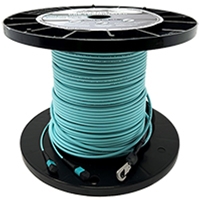
What Industries Does MTP Work Best With?
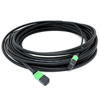
Indoor MTP Trunks
Indoor MTP trunks are ideal for high-density fiber networks within buildings, such as data centers and telecom rooms. Designed for flexible routing, they feature fire-rated jackets (LSZH or OFNP) for safety and protection. These pre-terminated cables ensure quick deployment, low insertion loss, and reliable performance. Choose QuickTreX Indoor MTP Trunks for a secure, efficient, and high-speed fiber optic solution.
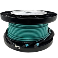
Indoor/Outdoor MTP Trunks
Indoor/Outdoor MTP trunks provide a versatile solution for fiber networks that require both indoor and outdoor connectivity. These cables feature rugged, weather-resistant jackets to withstand harsh environmental conditions while maintaining flexibility for indoor routing. With UV and moisture resistance, they ensure durability and long-term performance. Choose QuickTreX Indoor/Outdoor MTP Trunks for a reliable, high-speed fiber optic connection that seamlessly transitions between indoor and outdoor environments.
Indoor Armored MTP Trunks
Indoor Armored MTP Trunks offer superior protection for high-density fiber networks in indoor environments where durability is essential. These cables feature a robust armored layer that safeguards against crushing, impact, and rodent damage while eliminating the need for additional conduit. Despite their strength, they remain flexible for easy installation in tight spaces. Choose QuickTreX Indoor Armored MTP Trunks for enhanced security, longevity, and reliable performance in demanding indoor applications.
Indoor/Outdoor Armored MTP Trunks
Indoor/Outdoor Armored MTP Trunks provide the ultimate durability and versatility for fiber networks that transition between indoor and outdoor environments. These cables feature a rugged armored layer that protects against moisture, UV exposure, extreme temperatures, crushing, and rodent damage, ensuring long-lasting performance in harsh conditions. Despite their toughness, they remain flexible and easy to install. Choose QuickTreX Indoor/Outdoor Armored MTP Trunks for a seamless, high-performance fiber solution that withstands both indoor and outdoor challenges.
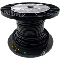
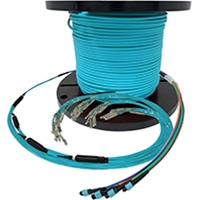
Outdoor Loose Tube MTP Trunks
Outdoor Loose Tube MTP Trunks are designed for superior performance in harsh outdoor environments. Their loose tube construction protects fiber strands from water ingress, temperature fluctuations, and mechanical stress, making them ideal for long-distance, direct-buried, or aerial installations. With a durable, water-blocking design, these trunks prevent fiber damage caused by moisture and environmental exposure. Choose QuickTreX Outdoor Loose Tube MTP Trunks for a reliable, high-capacity fiber optic solution built to withstand extreme outdoor conditions.
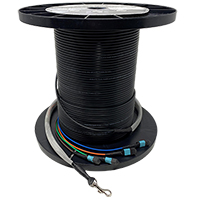
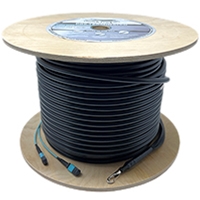
Outdoor Self-Supporting Drop MTP Trunks
Outdoor Self-Supporting Drop MTP Trunks are engineered for aerial installations where a durable, all-in-one solution is needed. Featuring an integrated messenger wire, these trunks provide superior tensile strength, eliminating the need for additional support hardware. Designed to withstand harsh outdoor conditions, they offer excellent resistance to weather, UV exposure, and mechanical stress. Choose QuickTreX Outdoor Self-Supporting Drop MTP Trunks for a reliable, high-performance fiber optic solution in aerial deployment applications.
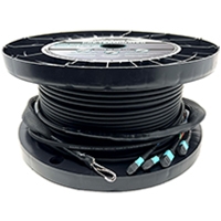
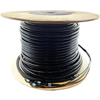
Outdoor Armored MTP Trunks
Outdoor Armored MTP Trunks are designed for rugged outdoor environments where additional protection is required. Built with a durable armored layer, these trunks offer superior resistance to moisture, rodents, and physical impact, ensuring long-term reliability in harsh conditions. Their robust construction makes them ideal for direct burial, conduit, or industrial applications. Choose QuickTreX Outdoor Armored MTP Trunks for maximum durability and protection in demanding outdoor fiber optic installations.
IP68 Weatherproof OptiTip® HMFC
IP68 Weatherproof OptiTip® HMFC is the ideal choice for harsh outdoor environments where maximum protection against water, dust, and extreme weather conditions is required. Designed with an IP68-rated sealed housing, it ensures a secure, reliable connection in underground, aerial, and industrial applications. This rugged solution is perfect for fiber-to-the-home (FTTH), telecom, and military-grade deployments, offering durability and high performance in the toughest conditions. Choose QuickTreX IP68 Weatherproof OptiTip® HMFC for unmatched reliability in outdoor MTP fiber optic networks.
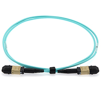
Stock Indoor MPO Cables
Stock Indoor MPO Cables are the perfect choice for fast, high-performance fiber deployments in data centers and enterprise networks. These pre-terminated cables provide a plug-and-play solution, reducing installation time and ensuring precise connectivity with minimal signal loss. Designed for indoor environments, they offer compact, high-density connectivity, making them ideal for structured cabling, networking racks, and high-speed backbone applications. Choose QuickTreX Stock Indoor MPO Cables for a reliable, ready-to-ship fiber solution that meets industry standards for performance and efficiency.
Stock Indoor/Outdoor MTP/MPO Trunk
Stock Indoor/Outdoor MTP/MPO Trunk Cables offer a versatile, high-performance solution for fiber optic networks that require both indoor and outdoor connectivity. Designed to withstand environmental factors such as moisture, temperature changes, and UV exposure, these cables ensure reliable, low-loss transmission in diverse conditions. Their rugged yet flexible construction makes them ideal for data centers, campus networks, and enterprise backbones, allowing seamless transitions between indoor and outdoor installations. Choose QuickTreX Stock Indoor/Outdoor MTP/MPO Trunk Cables for a ready-to-ship, durable, and high-density fiber networking solution.
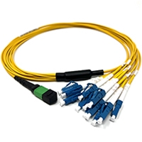
Indoor MTP Fanouts
Indoor MTP Fanouts are the ideal solution for efficiently breaking out high-density MTP connections into individual fiber strands for patching into switches, transceivers, or patch panels. Designed for controlled indoor environments, these fanouts provide precise, low-loss connections while maintaining a clean and organized cable management system. Their compact and flexible design makes them perfect for data centers, telecom rooms, and enterprise networks, ensuring seamless integration with existing infrastructure. Choose QuickTreX Indoor MTP Fanouts for a reliable, high-performance, and space-saving fiber optic breakout solution.
Indoor / Outdoor MTP Fanouts
Indoor/Outdoor MTP Fanouts provide a versatile solution for high-density fiber networks that require seamless transitions between indoor and outdoor environments. Engineered with ruggedized materials for UV, moisture, and temperature resistance, these fanouts ensure long-lasting durability and optimal performance in challenging conditions. Ideal for campus networks, outdoor enclosures, and building-to-building connections, they maintain low-loss, high-speed data transmission while offering flexibility in deployment. Choose QuickTreX Indoor/Outdoor MTP Fanouts for a reliable, weather-resistant, and efficient fiber optic breakout solution.
MTP OSP Loose Tube Fanout Cable
MTP OSP Loose Tube Fanout Cable is designed for outdoor service provider (OSP) applications, offering superior durability and protection in harsh environments. Its loose tube construction safeguards fiber strands from moisture, temperature fluctuations, and mechanical stress, making it ideal for long-distance outdoor installations, underground ducts, and direct burial applications. With UV-resistant, water-blocking, and ruggedized materials, this cable ensures low-loss performance and long-term reliability. Choose QuickTreX MTP OSP Loose Tube Fanout Cable for high-density, weather-resistant, and mission-critical fiber connectivity in outdoor networks.
MTP OSP Armored Fanout Cable
MTP OSP Armored Fanout Cable is the ultimate choice for outdoor deployments requiring maximum durability and protection. Designed for harsh environments, its armored construction shields fibers from rodents, impact, moisture, and extreme weather conditions, ensuring long-lasting performance in underground, aerial, and direct burial applications. The loose tube design with water-blocking technology prevents fiber damage, while the MTP fanout termination allows for seamless integration into high-density networks. Choose QuickTreX MTP OSP Armored Fanout Cable for rugged, high-performance, and reliable outdoor fiber connectivity.
Stock Indoor MPO Fanout Cables
Stock Indoor MPO Fanout Cables are the ideal solution for quick deployment in high-density network environments. Designed for fast and efficient connections, these cables eliminate the need for time-consuming field terminations, ensuring seamless integration with patch panels, switches, and active equipment. Their compact and flexible design makes them perfect for data centers, telecom rooms, and enterprise networks. With pre-terminated MPO connectors and high-quality fanout strands, they provide low insertion loss, reliable performance, and easy scalability. Choose QuickTreX Stock Indoor MPO Fanout Cables for cost-effective, ready-to-ship fiber connectivity.
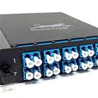
Cassettes and Components
Cassettes and Components are essential for organizing and managing high-density fiber networks while maintaining proper polarity and secure connections. These pre-terminated units simplify installation, reduce downtime, and ensure optimal performance by efficiently distributing fiber strands from MTP/MPO trunk cables to standard LC, SC, or other connectors. Designed for data centers, enterprise networks, and telecom applications, they provide modular, scalable, and space-saving solutions. QuickTreX cassettes and components are built for seamless integration, superior fiber alignment, and long-term reliability, making them the best choice for structured cabling systems and future-proof networking.
Which Products Might You Need Based On Your Industry?
Data Centers & Cloud Providers
Data centers and cloud providers rely on MTP/MPO fiber optic solutions for high-speed, high-density, and scalable connectivity to support increasing bandwidth demands. Indoor MTP trunks and fanouts optimize fiber management within racks, while armored and outdoor-rated MTP trunks ensure durability and protection in high-traffic or harsh environments. Choosing the right MTP/MPO solution guarantees efficient, reliable, and future-proof network performance for modern cloud and data infrastructure.
Large Enterprise Campuses
Enterprises require scalable and high-bandwidth fiber networks to support large-scale operations, data centers, and interconnected office buildings. Indoor MTP trunks and fanouts enable seamless network expansion and optimized fiber management.
Telecommunications & ISPs
Telecom providers and ISPs rely on MTP/MPO solutions to handle high-speed broadband, 5G networks, and fiber-to-the-home (FTTH) deployments. Outdoor armored MTP trunks ensure durability in harsh environments, while indoor solutions streamline data center connectivity.
Artificial Intelligence
AI-driven applications, including machine learning, big data analytics, and high-performance computing, demand ultra-low latency and high-bandwidth fiber networks. High-density MTP/MPO solutions help optimize interconnectivity between servers and data storage units.
Financial Services & Stock Exchanges
The financial sector requires high-speed, ultra-low latency networks to support real-time transactions, trading platforms, and data analytics. Indoor armored MTP trunks offer reliable connectivity while reducing downtime risks.
Media & Entertainment
High-resolution video production, streaming, and broadcasting require high-speed, low-latency fiber networks to handle massive data transfers. MTP/MPO fanouts and cassettes enable seamless connectivity in editing studios, broadcast stations, and cloud storage systems.
Government & Military
Mission-critical applications demand secure, high-performance fiber networks for data transmission, surveillance, and communication systems. Armored MTP/MPO solutions provide enhanced durability and protection in harsh environments.
Healthcare & Medical Imaging
Hospitals and research facilities require high-bandwidth, low-latency networks to support MRI scans, telemedicine, and patient data management. MTP/MPO solutions enhance connectivity between medical imaging devices, data centers, and cloud-based systems.
Smart Cities & IoT
The rise of IoT and smart city infrastructure demands high-speed fiber networks for traffic management, security systems, and real-time data analytics. Outdoor MTP/MPO cables ensure reliable connectivity across urban environments.
MTP Accessories
There are a variety of hardware accessories that go along with most MTP/MTO installations. It's important to match what you need with what you have for maximum performance and full compatibility.
MTP Coupler
An MTP coupler is used to connect two 12 fiber MTP male to MTP female connectors together.
MTP Adapter Panel
This can also be accomplished using an MTP adapter panel which will have 6 or 8 MTP/MTO couplers within the panel. This is useful to connect an MTP assembly with an MTP Fanout cable - Male to Female Connections
MTP Cassette
A cassette will have an MTP connector in the back which will be a male connector. Therefore, MTP cables that plug into the cassettes will be a female cable.
MTP Cabling and Fanouts
Matching your MTP trunk assembly to the appropriate fanout cabling situation isn't always simple. Here are some of the choices for what you might need to match with what you have for maximum performance and full compatibility.
Pulling Eyes
A pulling eye is designed to be attached to a pull string that runs the full length of your conduit. Your assembly is then pulled through the conduit via the pull string. It can also be used to pull your assembly through duct work, in wall cavities, or other areas where routing needs to take place. Our pulling eyes include a heavy-duty swivel hook to prevent the cable from twisting during the pull. The metal pull hook is attached to a designated pull string inside of your assembly usually consisting of Kevlar so that you are not pulling on the fiber strands themselves. The pulling eye includes heat shrink tubing that covers the back side of the pull hook, and the pull basket that contains your fiber optic connectors.
The pull basket is constructed with super strong polyethylene mesh that tightens itself around the strands and connectors keeping them securely in place during install. The connectors are also staggered inside of the pull basket for less bulk, and each connector is individually plastic wrapped to prevent contamination by pulling lubricants and other debris. Our pulling eyes are always recommended as they make your pull much easier while providing further protection of your connectors.
Chassis Types
There are three popular MTP strand counts available on the market today.
These MTP®/MPO cassettes will fit most standard LGX Fiber Optic Enclosures that include enough depth to accommodate the MTP assembly in the back of it.
Note: All LGX rack mount enclosures are compatible and 2-12 panel LGX wall mount enclosures are compatible
These MPO cassettes will only fit SHD fiber optic enclosures and are great for high strand count installs typically seen in data centers, campuses, and other commercial settings. Note: SHD enclosures are only available in rack mount style. We offer a 5 panel (1U) and 14 panel (2U).
Strands
When selecting the “strand” count on the MTP Cassette Configurator, it is important to match the MTP/MPO connector type with the correct cassette.
For instance, if you are ordering a 1x 24 MTP Assembly, then that cable would not be compatible with a 2 x 12 MTP cassette. Both examples utilize 24 fibers but are wired differently.
A single 24 fiber MTP connector will specifically require an MTP Cassette that accepts 1 x 24. An assembly that has 2 x 12 MTP connectors, would need a cassette that accepts two 12 fiber MTP connectors.

Follow us on Social Media for top networking tips!