SALES & ORDERS
Custom Cable Manufacturing in the USA Since 1997
Home of 
Free Ground shipping on orders over $250

Use code SHIP4FREE Exclusions Apply
Important!
Eligible Products Only | Free Shipping Exclusions May Apply to Heavy, Electronics & Bulky Items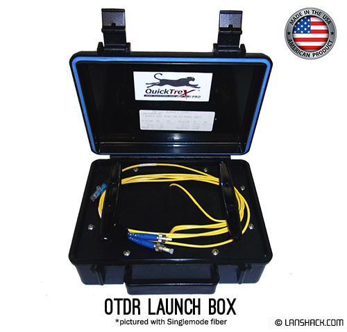


Add Related Products

Pre-Term Fiber Assemblies
MTP Trunk Assemblies

MTP Fanout Cables

MTP Cassettes

Fiber Optic Enclosures
Fiber Optic Patch Cables
Ethernet Patch Cables

Ethernet Cable Bundles
Unterminated Fiber By The Foot
Network Configurator™
Use LANShack’s state of the art network designer tool to completely build your network from scratch.

What product are you looking for?
Pre-Term Fiber Assemblies
MTP Trunk Assemblies
MTP Fanout Cables
MTP Cassettes
Fiber Optic Enclosures
Fiber Optic Patch Cables
Ethernet Patch Cables
Ethernet Cable Bundles
Unterminated Fiber By The Foot
OTDRs are used on outside plant cables to check the loss of each splice and locate any stress points that were caused during installation. OTDRs use the backscattered light of the fiber to indicate loss. With an installed cable plant the OTDR trace will show every connector splice, break, and anomaly in the fiber.
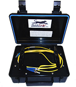
The OTDR Launch Box acts as a companion to OTDR test equipment. There are a few reasons to use a launch box (also know as a “launch cable” or “pulse suppressor”). One, the launch cable helps avoid problems with the dead zone, or the area close to the OTDR which causes an overload from the crosstalk between the instrument and the reflectance from the connector face of the OTDR. The long recovery time means the OTDR cannot make useful measurements near the instrument itself. The launch cable allows time for the OTDR trace to settle down after the test pulse is sent into the fiber so the beginning of the cable being tested can be analyzed.
Second the launch cable provides a reference to push out the first connector of the cable under test so that a picture of the fiber can be taken, as it acts as a reference point for the first connector on the cable under test to determine its loss.
The assembly in the launch box is a simplex bare glass fiber which is a specified length (generally 100 meters for Multimode and 300 meters for Singlemode). The fiber is a fixed length and is terminated with one connector type for the OTDR and the other to match the coupler that the cable under test will be plugged into. The connectors have a standard UPC polish, but APC polish can be added to SC, LC, or FC connectors. The fiber and the connectors are both Genuine Corning brand material, and this product is made in the USA at the time of the order to your specifications. If you need a lenght that is not a standard option, just email [email protected] for a custom quote.
Specs:
Applicable Temperature Restrictions:
Storage temperature: -40 to +70degrees Celsius
Operating temperature: 0 to +70degrees Celsius
Multimode 62.5/125 (850/ 1300nm)
Max attenuation (dB/km): 3.75/1.5
Typical attenuation (dB/km) : 3.0/1.0
Multimode 50 /125 (850/ 1300nm)
Max attenuation (dB/km): 3.5/1.5
Typical attenuation (dB/km) : 3.0/1.0
Singlemode (1310/ 1550nm)
Max attenuation (dB/km): 1.0/.75
Typical attenuation (dB/km) : 0.5/0.4
Connector Physical Contact Specifications:
All terminations measured per BELLCORE GR-326-CORE
Typical radius of curvature 10-30nm
Typical apex offset < 50uM
Fiber undercut/protrusion +/- 50nM
Maximum insertion loss -.5dB
Typical return loss -55dB
Case Composition:
High density polyethylene
Neoprene enviromental seal O-ring
Butterfly twist latches
Spring-loaded handle
Meets ATA-300, Category 1, & Certain Military Specifications
Videos
When You Place An Order

Step 01
Place Your Order
Our team processes your order within 24 business hours.

Step 02
Get Notifications
You receive emails about your order status.

Step 03
Track Your Order
Get tracking on your shipment until delivery.
Product Reviews (18)
5
5
4
3
2
1
WHEELER ELECTRIC
Quick and thorough order completion - had exactly what we needed - right price and right on time!!!
GARG
First class product and service
Kathy E.
prompt service, quick shipping, all parts arrived in good condition
Bill Zantopulos
Very reliable supplier of products. #1 in my book!
Peter Ruiz
Awesome Service
Don’t Just Take Our Word For It
Jun 30, 2026
Leslie and Lauren were both very…
Leslie and Lauren were both very helpful with helping me with my first big order.
Chris P, RCDD
Feb 17, 2026
LANshack: Best custom CAT8 ethernet cable on the market!
I needed a custom 55 foot S/FTP (Shielded Foiled Twisted Pair) CAT8 indoor ethernet cable for ethernet backhaul between two Eero mesh routers. I did tons of research (including Grok) and I came across LANshack.com. They have the thickest 23AWG wire in their custom CAT8 cable vs 26AWG on Amazon (lower number is thicker; 23AWG wire has roughly twice the cross-sectional area of 26AWG). Excellent price per foot, and this cable is thick! Very quick turnaround once you order from them. I am very pleased with LANshack and I will order from them again for future projects!
Daniel T.
Jul 12, 2026
reliable products and good customer…
reliable products and good customer service
Junior L.
Apr 14, 2026
Product was received on time and…
Product was received on time and quality was what was expected
customer
Apr 28, 2026
always get items in a timely manner…
always get items in a timely manner with no problems and cables are always great with no problems.
customer
Mar 03, 2026
First time ordering and everything was…
First time ordering and everything was pretty smooth. Ordering was a breeze, was given plenty of updates on the shipment and all arrived in good timing.
Brannon Clark
Apr 14, 2026
Great Custom Cables
Great product, exactly what I needed and fairly quick shipping considering they are custom cables! Will definitely be ordering more.
Matt S
Jun 30, 2026
We got the order delivered on time and…
We got the order delivered on time and worked perfectly. Have used them multiple times and the quality is great and was a good value.
Code Red Audits LLC
Jun 10, 2026
All the items arrived in a timely…
All the items arrived in a timely manner, and the quality of them is outstanding. We are a Network Operations team in Alaska, and the fact that LANshack got the gear we ordered and the quality we expected in such a timely manner is a great success; we'll definitely be coming back to use your services.
customer
May 05, 2026
Very simple process when ordering…
Very simple process when ordering custom fiber cables.
Ron
Jan 21, 2026
Excellent customer service!
Excellent customer service!
customer
Jul 18, 2026
Easy ordering process
Easy ordering process. Fast delivery! Will definitely use them again.
Roger Borlinghaus
Apr 14, 2026
My go-to place for networking gear.
My go-to place for networking gear.
Jim
Apr 02, 2026
Easily ordered exactly what I needed
Easily ordered exactly what I needed. Once I got a shipping label item was delivered quickly and was packaged nicely. Would order from here again.
customer
May 20, 2026
Cables made quick.
Ordering process was quick and easy shipping was lightning fast product was excellently made
customer
May 14, 2026
Quick service
Quick service. And good products!
Dw
Jul 21, 2026
I ordered MTP/MPO special order Fiber…
I ordered MTP/MPO special order Fiber and cassettes. All merchandise came in perfect condition. The Fiber was easy rollout. I am 100% satisfied and will do business again with LANshack! They will be my first choice on all my installations!
TriSight. Inc.
Jun 18, 2026
Easy to order with good shipping
Easy to order with good shipping
Samuel Monroe
Jun 30, 2026
First time user of LANshack
First time user of LANshack. I couldn’t be more impressed from ordering to time turnaround to delivery to final product first class act all the way.
customer
Feb 28, 2026
Product was as described
Product was as described. Reasonable shipping and well packaged. Price was appropriate.
customer
Read 1,459 reviews on
