![]() Our Administrative Offices will be Closed July 4th and 5th. Have a Safe and Happy Holiday!
Our Administrative Offices will be Closed July 4th and 5th. Have a Safe and Happy Holiday! ![]()


 888-568-1230
Fast Lead Times | Fast Shipping


Fiber Optic Testing
After the cables are installed and terminated, it's time for testing. For every fiber optic cable plant, you will need to test for continuity, end-to-end loss and then troubleshoot the problems. If it's a long outside plant cable with intermediate splices, you will probably want to verify the individual splices with an OTDR also, since that's the only way to make sure that each one is good. If you are the network user, you will also be interested in testing power, as power is the measurement that tells you whether the system is operating properly.
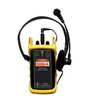
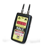
You'll need a few special tools and instruments to test fiber optics. See Jargon in the beginning of Lennie's Guide to see a description of each instrument.
Getting Started
Even if you're an experienced installer, make sure you remember these things.
1. Have the right tools and test equipment for the job. You will need:
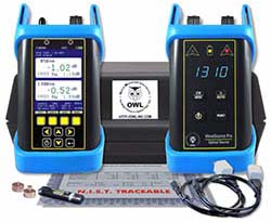
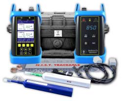
1. Source and power meter, optical loss test set or test kit with proper equipment adapters for the cable plant you are testing.
2. Reference test cables that match the cables to be tested and mating adapters, including hybrids if needed.
3. Fiber Tracer or Visual Fault Locator.
4. Cleaning materials - lint free cleaning wipes and pure alcohol.
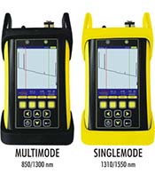
5. OTDR and launch cable for outside plant jobs.
2. Know how to use your test equipment
Before you start, get together all your tools and make sure they are all working properly and you and your installers know how to use them. It's hard to get the job done when you have to call the manufacturer from the job site on your cell phone to ask for help. Try all your equipment in the office before you take it into the field. Use it to test every one of your reference test jumper cables in both directions using the single-ended loss test to make sure they are all good. If your power meter has internal memory to record data be sure you know how to use this also. You can often customize these reports to your specific needs - figure all this out before you go it the field - it could save you time and on installations, time is money!
3. Know the network you're testing...
This is an important part of the documentation process we discussed earlier. Make sure you have cable layouts for every fiber you have to test. Prepare a spreadsheet of all the cables and fibers before you go in the field and print a copy for recording your test data. You may record all your test data either by hand or if your meter has a memory feature, it will keep test results in on-board memory that can be printed or transferred to a computer when you return to the office.
A note on using a fiber optic source eye safety...
Fiber optic sources, including test equipment, are generally too low in power to cause any eye damage, but it's still a good idea to check connectors with a power meter before looking into it. Some telco DWDM and CATV systems have very high power and they could be harmful, so better safe than sorry.
Fiber optic testing includes three basic tests that we will cover separately: Visual inspection for continuity or connector checking, Loss testing, and Network Testing.
Visual Inspection/ Visual Tracing
Continuity checking makes certain the fibers are not broken and to trace a path of a fiber from one end to another through many connections. Use a visible light "fiber optic tracer" or "pocket visual fault locator". It looks like a flashlight or a pen-like instrument with a lightbulb or LED soure that mates to a fiber optic connector. Attach a cable to test to the visual tracer and look at the other end to see the light transmitted through the core of the fiber. If there is no light at the end, go back to intermediate connections to find the bad section of the cable.
A good example of how it can save time and money is testing fiber on a reel before you pull it to make sure it hasn't been damaged during shipment. Look for visible signs of damage (like cracked or broken reels, kinks in the cable, etc.) . For testing, visual tracers help also identify the next fiber to be tested for loss with the test kit. When connecting cables at patch panels, use the visual tracer to make sure each connection is the right two fibers! And to make certain the proper fibers are connected to the transmitter and receiver, use the visual tracer in place of the transmitter and your eye instead of the receiver (remember that fiber optic links work in the infrared so you can't see anything anyway.)
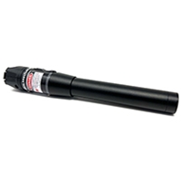
Visual Fault Location
A higher power version of the tracer uses a laser that can also find faults. The red laser light is powerful enough to show breaks in fibers or high loss connectors. You can actually see the loss of the bright red light even through many yellow or orange simplex cable jackets except black or gray jackets. You can also use this gadget to optimize mechanical splices or prepolished-splice type fiber optic connectors. In fact- don't even think of doing one of those connectors without one no other method will assure you of high yield with them.
Visual Connector Inspection
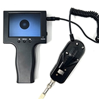
Fiber optic microscopes are used to inspect connectors to check the quality of the termination procedure and diagnose problems. A well made connector will have a smooth , polished, scratch free finish and the fiber will not show any signs of cracks, chips or areas where the fiber is either protruding from the end of the ferrule or pulling back into it.
The magnification for viewing connectors can be 30 to 400 power but it is best to use a medium magnification. The best microscopes allow you to inspect the connector from several angles, either by tilting the connector or having angle illumination to get the best picture of what's going on. Check to make sure the microscope has an easy-to-use adapter to attach the connectors of interest to the microscope.
And remember to check that no power is present in the cable before you look at it in a microscope protect your eyes!
Optical Power - Power or Loss? ("Absolute" vs. "Relative")
Practically every measurement in fiber optics refers to optical power. The power output of a transmitter or the input to receiver are "absolute" optical power measurements, that is, you measure the actual value of the power. Loss is a "relative" power measurement, the difference between the power coupled into a component like a cable or a connector and the power that is transmitted through it. This difference is what we call optical loss and defines the performance of a cable, connector, splice, etc.
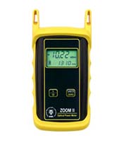
Measuring power
Power in a fiber optic system is like voltage in an electrical circuit - it's what makes things happen! It's important to have enough power, but not too much. Too little power and the receiver may not be able to distinguish the signal from noise; too much power overloads the receiver and causes errors too.
Measuring power requires only a power meter (most come with a screw-on adapter that matches the connector being tested) and a little help from the network electronics to turn on the transmitter. Remember when you measure power, the meter must be set to the proper range (usually dBm, sometimes microwatts, but never "dB" that's a relative power range used only for testing loss!) and the proper wavelengths matching the source being used. Refer to the instructions that come with the test equipment for setup and measurement instructions (and don't wait until you get to the job site to try the equipment)!
To measure power, attach the meter to the cable that has the output you want to measure. That can be at the receiver to measure receiver power, or to a reference test cable (tested and known to be good) that is attached to the transmitter, acting as the "source", to measure transmitter power. Turn on the transmitter/source and note the power the meter measures. Compare it to the specified power for the system and make sure it's enough power but not too much.
Testing loss
Loss testing is the difference between the power coupled into the cable at the transmitter end and what comes out at the receiver end. Testing for loss requires measuring the optical power lost in a cable (including connectors ,splices, etc.) with a fiber optic source and power meter by mating the cable being tested to known good reference cable.
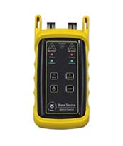
In addition to our power meter, we will need a test source. The test source should match the type of source (LED or laser) and wavelength (850, 1300, 1550 nm). Again, read the instructions that come with the unit carefully.
We also need one or two reference cables, depending on the test we wish to perform. The accuracy of the measurement we make will depend on the quality of your reference cables. Always test your reference cables by the single ended method shown below to make sure they're good before you start testing other cables!
Next we need to set our reference power for loss our "0 dB" value. Correct setting of the launch power is critical to making good loss measurements!
Clean your connectors and set up your equipment like this:
Turn on the source and select the wavelength you want for the loss test. Turn on the meter, select the "dBm" or "dB" range and select the wavelength you want for the loss test. Measure the power at the meter. This is your reference power level for all loss measurements. If your meter has a "zero" function, set this as your "0" reference.
Some reference books and manuals show setting the reference power for loss using both a launch and receive cable mated with a mating adapter. This method is acceptable for some tests, but will reduce the loss you measure by the amount of loss between your reference cables when you set your "0dB loss" reference. Also, if either the launch or receive cable is bad, setting the reference with both cables hides the fact. Then you could begin testing with bad launch cables making all your loss measurements wrong. EIA/TIA 568 calls for a single cable reference, while OFSTP-14 allows either method.
Testing Loss
There are two methods that are used to measure loss, which we call "single-ended loss" and "double-ended loss". Single-ended loss uses only the launch cable, while double-ended loss uses a receive cable attached to the meter also.
Single-ended loss is measured by mating the cable you want to test to the reference launch cable and measuring the power out the far end with the meter. When you do this you measure 1. the loss of the connector mated to the launch cable and 2. the loss of any fiber, splices or other connectors in the cable you are testing. This method is described in FOTP-171 and is shown in the drawing. Reverse the cable to test the connector on the other end.
In a double-ended loss test, you attach the cable to test between two reference cables, one attached to the source and one to the meter. This way, you measure two connectors' loses, one on each end, plus the loss of all the cable or cables in between. This is the method specified in OFSTP-14, the test for loss in an installed cable plant.
What Loss Should You Get When Testing Cables?
While it is difficult to generalize, here are some guidelines:
- For each connector, figure 0.5 dB loss (0.7 max)
- For each splice, figure 0.2 dB
- For multimode fiber, the loss is about 3 dB per km for 850 nm sources, 1 dB per km for 1300 nm. This roughly translates into a loss of 0.1 dB per 100 feet for 850 nm, 0.1 dB per 300 feet for 1300 nm.
- For singlemode fiber, the loss is about 0.5 dB per km for 1300 nm sources, 0.4 dB per km for 1550 nm.
This roughly translates into a loss of 0.1 dB per 600 feet for 1300 nm, 0.1 dB per 750 feet for 1300 nm. So for the loss of a cable plant, calculate the approximate loss as:
(0.5 dB X # connectors) + (0.2 dB x # splices) + fiber loss on the total length of cable
Troubleshooting Hints:
If you have high loss in a cable, make sure to reverse it and test in the opposite direction using the single-ended method. Since the single ended test only tests the connector on one end, you can isolate a bad connector - it's the one at the launch cable end (mated to the launch cable) on the test when you measure high loss.
High loss in the double ended test should be isolated by retesting single-ended and reversing the direction of test to see if the end connector is bad. If the loss is the same, you need to either test each segment separately to isolate the bad segment or, if it is long enough, use an OTDR.
If you see no light through the cable (very high loss - only darkness when tested with your visual tracer), it's probably one of the connectors, and you have few options. The best one is to isolate the problem cable, cut the connector of one end (flip a coin to choose) and hope it was the bad one (well, you have a 50-50 chance!)
OTDR Testing
As we mentioned earlier, OTDRs are always used on OSP cables to verify the loss of each splice. But they are also used as troubleshooting tools. Let's look at how an OTDR works and see how it can help testing and troubleshooting.
How OTDRs Work
Unlike sources and power meters which measure the loss of the fiber optic cable plant directly, the OTDR works indirectly. The source and meter duplicate the transmitter and receiver of the fiber optic transmission link, so the measurement correlates well with actual system loss.
The OTDR, however, uses backscattered light of the fiber to imply loss. The OTDR works like RADAR, sending a high power laser light pulse down the fiber and looking for return signals from backscattered light in the fiber itself or reflected light from connector or splice interfaces.
At any point in time, the light the OTDR sees is the light scattered from the pulse passing through a region of the fiber. Only a small amount of light is scattered back toward the OTDR, but with sensitive receivers and signal averaging, it is possible to make measurements over relatively long distances. Since it is possible to calibrate the speed of the pulse as it passes down the fiber, the OTDR can measure time, calculate the pulse position in the fiber and correlate what it sees in backscattered light with an actual location in the fiber. Thus it can create a display of the amount of backscattered light at any point in the fiber.
Since the pulse is attenuated in the fiber as it passes along the fiber and suffers loss in connectors and splices, the amount of power in the test pulse decreases as it passes along the fiber in the cable plant under test. Thus the portion of the light being backscattered will be reduced accordingly, producing a picture of the actual loss occurring in the fiber. Some calculations are necessary to convert this information into a display, since the process occurs twice, once going out from the OTDR and once on the return path from the scattering at the test pulse.
There is a lot of information in an OTDR display. The slope of the fiber trace shows the attenuation coefficient of the fiber and is calibrated in dB/km by the OTDR. In order to measure fiber attenuation, you need a fairly long length of fiber with no distortions on either end from the OTDR resolution or overloading due to large reflections. If the fiber looks nonlinear at either end, especially near a reflective event like a connector, avoid that section when measuring loss.
Connectors and splices are called "events" in OTDR jargon. Both should show a loss, but connectors and mechanical splices will also show a reflective peak so you can distinguish them from fusion splices. Also, the height of that peak will indicate the amount of reflection at the event, unless it is so large that it saturates the OTDR receiver. Then peak will have a flat top and tail on the far end, indicating the receiver was overloaded. The width of the peak shows the distance resolution of the OTDR, or how close it can detect events.
OTDRs can also detect problems in the cable caused during installation. If a fiber is broken, it will show up as the end of the fiber much shorter than the cable or a high loss splice at the wrong place. If excessive stress is placed on the cable due to kinking or too tight a bend radius, it will look like a splice at the wrong location.
OTDR Limitations
The limited distance resolution of the OTDR makes it very hard to use in a LAN or building environment where cables are usually only a few hundred meters long. The OTDR has a great deal of difficulty resolving features in the short cables of a LAN and is likely to show "ghosts" from reflections at connectors, more often than not simply confusing the user.
Using The OTDR
When using an OTDR, there are a few cautions that will make testing easier and more understandable. First always use a long launch cable, which allows the OTDR to settle down after the initial pulse and provides a reference cable for testing the first connector on the cable. Always start with the OTDR set for the shortest pulse width for best resolution and a range at least 2 times the length of the cable you are testing. Make an initial trace and see how you need to change the parameters to get better results.
Restoration
The time may come when you have to troubleshoot and fix the cable plant. If you have a critical application or lots of network cable, you should be ready to do it yourself. Smaller networks can rely on a contractor. If you plan to do it yourself, you need to have equipment ready (extra cables, mechanical splices, quick termination connectors, etc., plus test equipment.) and someone who knows how to use it.
We cannot emphasize more strongly the need to have good documentation on the cable plant. If you don't know where the cables go, how long they are or what they tested for loss, you will be spinning you wheels from the get-go. And you need tools to diagnose problems and fix them, and spares including a fusion splicer or some mechanical splices and spare cables. In fact, when you install cable, save the leftovers for restoration! And the first thing you must decide is if the problem is with the cables or the equipment using it. A simple power meter can test sources for output and receivers for input and a visual tracer will check for fiber continuity. If the problem is in the cable plant, the OTDR is the next tool needed to locate the fault.
videos