


- MPO/MTP: Essential for 40G/100G migration and backbone high-density trunking.
- APC vs. UPC: APC (Green) is required for high-return loss sensitivity (e.g., FTTX/Video), while UPC (Blue) is standard for most enterprise data networks.
Introduction
Modern networks depend on speed, stability, and scalability. While switches and hardware often receive the most attention, experienced installers and network engineers know that long-term performance is decided much earlier at the physical layer. Fiber optic assemblies, connectors, and supporting infrastructure determine whether a deployment runs smoothly or becomes a troubleshooting project months later.
Across enterprise environments, data centers, and structured cabling installations, the same pattern appears repeatedly. Projects that succeed are not necessarily the ones using the most expensive equipment. They are the ones where fiber optics were selected with the installation environment, density requirements, and future expansion in mind.
This guide explains fiber optic assemblies and connectors from a practical deployment perspective. It focuses on real decisions installers, integrators, and IT teams make when building networks that are expected to perform reliably for years.
Why Most Fiber Issues Begin Before Installation
When a link fails certification testing, the immediate reaction is to inspect equipment or configuration. In reality, many problems originate during specification.
Common early mistakes include:
- Selecting fiber cables without considering the installation environment
- Mixing connector types across infrastructure upgrades
- Choosing field termination where consistency is critical
- Underestimating future bandwidth or density requirements
Fiber optics are extremely reliable when assemblies are matched correctly. Small planning decisions often determine whether installation is straightforward or requires ongoing adjustment after deployment.
How Fiber Optic Assemblies Work as a Complete System
A fiber cable carries light, but performance depends on how precisely that light moves between connection points. Connectors, termination quality, and assembly design all influence signal integrity.
In high-density or mission-critical environments, individual components cannot be treated separately. Fiber optic assemblies are engineered systems where cable construction, connector alignment, and testing standards work together.
This becomes especially important in:
- Data center expansions
- Enterprise backbone upgrades
- Harsh or industrial installation environments
- High port-density racks
Installers often discover that consistent, factory-terminated fiber optic assemblies reduce variability and simplify deployment workflows.
Why Fiber Optics Continue to Replace Copper Backbones
Copper still works well for short device connections, but modern backbone networks rely on fiber optics for better reliability and scalability. Because fiber transmits data using light, it supports longer distances with minimal interference and signal loss.
Fiber also enables more predictable performance, making it ideal for enterprise backbones, data centers and Internal building connectivity.
Key Deployment Advantages of Fiber
In practical deployments, fiber is chosen for stability as much as speed.
- Consistent performance over longer distances
- Immunity to electromagnetic interference
- Higher bandwidth scalability
- Lower long-term maintenance needs
The main benefit is not just faster networks, but dependable performance as infrastructure grows.
Singlemode vs Multimode Fiber: Making the Right Choice
The traditional explanation between singlemode vs multimode fiber focuses on distance, but experienced teams evaluate long‑term flexibility as well.
Singlemode Fiber for Scalable Infrastructure
Singlemode fiber is commonly used for backbone infrastructure and projects expected to scale. Many organizations deploy single mode assemblies today even for moderate distances to avoid future replacement.
Typical deployments:
- Campus connectivity
- Telecom infrastructure
- Internal building links
- Long lifecycle enterprise networks
Multimode Fiber for Cost-Efficient Interconnects
Multimode fiber remains practical inside controlled environments where distances are predictable and cost efficiency matters.
Typical deployments:
- Data centers
- Equipment interconnects
- Enterprise structured cabling
Connector Types and Deployment Scenarios
Connector selection affects installation efficiency more than many teams expect.
LC vs MPO/MTP Connector Selection Overview
|
Parameter |
LC Connector |
MPO/MTP Connector |
|
Fiber Count |
1 fiber (simplex) or 2 fiber (duplex) |
8, 12, 16, 24+ fibers |
|
Primary Use |
Device connections and patch panels |
Backbone trunking and high-density interconnects |
|
Density |
High |
Ultra-high |
|
Typical Interfaces |
SFP, SFP+, SFP28 |
QSFP, QSFP28, QSFP-DD |
|
Speed Support |
1G–25G typical |
40G / 100G / 400G |
|
Deployment Speed |
Standard patching |
Fast pre-terminated trunk installs |
|
Polarity Planning |
Simple duplex polarity |
Requires Type A, B, or C polarity management |
|
Best Fit |
Access layer and equipment links |
Data center spine-leaf and rack-to-rack backbone |
The comparison above highlights how connector choice depends largely on network density and deployment scale.
LC Connectors for High-Density Racks
LC connectors dominate modern enterprise and data center environments due to their compact footprint and support for high port density. The sections below explain where each connector type fits in real installation environments.
MPO and MTP Connectors for High-Speed Trunking
MPO and MTP connectors enable multi-fiber connectivity and support high-speed parallel optics. Pre-terminated MPO assemblies significantly reduce installation time in dense environments.
Legacy Connectivity: SC, ST, and FC Connectors
These connectors still appear in legacy infrastructure and specialized installations where compatibility requirements exist.

In real-world deployments, fiber performance rarely fails because of the glass — it fails because of planning decisions made before installation begins. I've seen projects where teams invested heavily in switches and optics but treated fiber assemblies as a commodity item. That's usually where problems start.
Connector selection, verified insertion loss, proper polarity planning, and matching the cable construction to the installation environment make a bigger long-term difference than most people expect. In high-density racks or backbone upgrades, factory-terminated assemblies eliminate a lot of variability and save hours of troubleshooting later.
The goal isn't just to pass certification on day one — it's to build infrastructure that remains stable and scalable five or ten years down the road.
Tom Damiano
Fiber Optic Specialist
Installation Practices That Protect Fiber Performance
Even high-quality assemblies can under perform if installation practices are ignored.
Best Practices for Verified Reliability
- Maintain minimum bend radius during routing
- Inspect and clean connectors before mating
- Verify polarity before final testing
- Use certified testing equipment for validation
How to Avoid Common Fiber Optic Challenges
Most fiber performance problems are not caused by hardware failure but by specification or installation errors. When assemblies are properly selected and handled, fiber links typically operate with very low failure rates over long service lifecycles.
Common causes of performance issues include:
- Connector contamination: Dust or microscopic particles on the ferrule end face can significantly increase insertion loss and back reflection, even when contamination is not visible to the eye.
- Incorrect fiber type selection: Mixing singlemode and multimode infrastructure or choosing the wrong cable specification for distance and optics can result in attenuation problems and failed certification tests.
- Field termination inconsistencies: Manual termination introduces variability in alignment and polish quality, often leading to higher insertion loss compared to factory-terminated assemblies.
- Excessive bending during installation: Tight bend radius creates micro-bending or macro-bending losses, reducing signal strength and long-term reliability.
Pre-terminated fiber optic assemblies help minimize these risks by providing factory-verified connector alignment, controlled polishing, and insertion-loss testing before deployment.
Future Direction of Fiber Infrastructure
Network density continues to increase as data demand and AI workloads grow. Infrastructure planning now focuses equally on performance and deployment efficiency.
Key trends include:
- Higher fiber counts per rack
- Plug-and-play pre-terminated assemblies
- Faster installation timelines
- Greater demand for scalable backbone infrastructure
Organizations increasingly prioritize solutions that simplify deployment while maintaining performance consistency.
Conclusion
Reliable networks are built through careful planning at the physical layer. Fiber optic assemblies, connector selection, and installation discipline directly influence long-term performance.
Teams that approach fiber optics as an engineered system experience faster deployments, fewer troubleshooting cycles, and infrastructure that scales confidently as demands grow. Choosing the right assemblies early often determines how successfully a network performs for years to come.
Frequently Asked Questions
Q1: What is the practical difference between singlemode and multimode fiber in enterprise deployments?
Singlemode fiber supports longer transmission distances and higher scalability, making it suitable for backbone infrastructure and future upgrades. Multi-mode fiber is typically used for shorter in-building links where distances are predictable and cost efficiency is important.
Q2: How much insertion loss is acceptable per connector in a fiber link?
Typical acceptable insertion loss ranges between 0.2 dB and 0.5 dB per connection depending on connector quality and application standards. High-performance assemblies often achieve lower values, improving overall link margin.
Q3: What causes high return loss in fiber optic connections?
Return loss is commonly caused by poor connector polishing, contamination, air gaps, or mismatched connector types. APC connectors are often used where minimizing reflection is critical.
Q4: What is the difference between UPC and APC connectors?
UPC connectors use a flat polish commonly applied in standard data networking, while APC connectors use an angled polish designed to reduce optical reflection in sensitive transmission environments.
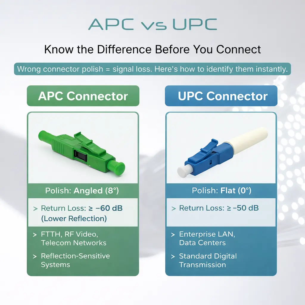
The key performance and deployment differences are summarized in the comparison below.
APC vs UPC: Choosing the Right Fiber Connector Polish
|
Parameter |
UPC Connector (Blue) |
APC Connector (Green) |
|
End-Face Geometry |
Flat polish (0°) with slight curvature |
8° angled polish |
|
Return Loss (Reflection Control) |
≥ −50 dB |
≥ −60 dB (lower reflection) |
|
Insertion Loss |
Typically ≤ 0.3 dB |
Typically ≤ 0.3 dB |
|
Reflection Behavior |
Light reflects back toward source |
Reflected light redirected into cladding |
|
Common Deployments |
Enterprise LAN, data centers |
FTTH, RF video, telecom networks |
|
Signal Sensitivity Suitability |
Standard digital transmission |
Reflection-sensitive optical systems |
|
Connector Compatibility |
Must mate with UPC |
Must mate with APC only |
|
Visual Identification |
Blue housing |
Green housing |
Q5: How do MPO and MTP connectors differ technically?
MPO is the general multi-fiber connector standard, while MTP is an enhanced version engineered for tighter tolerances, improved alignment, and lower insertion loss, making it better suited for high-speed data center applications.
Q6: What bend radius should be maintained during installation?
A general rule is maintaining a bend radius of at least 10 times the cable diameter during installation and 15 times during pulling to prevent micro-bending losses.
Q7: How often should fiber connectors be cleaned?
Best practice is to inspect and clean connectors before every mating, even if protective caps were used. Microscopic contamination is one of the leading causes of signal loss.
Q8: What testing methods are commonly used after installation?
Technicians typically use optical loss test sets (OLTS) for certification and OTDR testing to locate faults, splices, or excessive attenuation along the fiber run.
Q9: What factors influence fiber optic assembly lifespan?
Environmental exposure, cable handling, connector cleanliness, and installation quality all affect longevity. Properly installed assemblies often operate reliably for decades.
Q10: How does polarity impact MPO deployments?
Incorrect polarity configuration can prevent transmit and receive signals from aligning. Proper planning using Type A, B, or C polarity methods is critical for multi-fiber systems.